|
|
|
|||||||
| Mini Buggy General Discussion General Discussion forum for Mini Buggies. (American Sportworks, HammerHead, Carter, etc) |

 |
|
|
Thread Tools |
|
#1
 10-16-2012, 08:02 PM
|
|||
|
|||
|
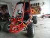
Hello everybody! I have read through quite a lot of posts here, and am happy to find how helpful everybody is. I was hoping to get some input/help from you knowledgeable fellas.
My son and I bought a Spiderbox minus the motor from a guy locally for $150. It seems to be in fairly decent shape. I have realized since reading here I will inevitably have to put some money into the front end to make it a great buggy, but I'm just concentrating on getting it rolling and running first. The only obvious thing wrong with it is the front right wheel bearings are blown out, and the passenger side needs new seat belts. There was also a bundle of wires in a pile that was induced the pic is attached. I bought a GY6 motor from ebay. http://www.ebay.com/itm/SHORT-CASE-1...390759?vxp=mtr I got the motor today, and I'm hoping that my 2 years of automotive courses in high school will be enough to get me through this project. A few of the wires and parts that came with the motor are not immediately obvious to me where they go... I ordered new bearings and castle nut for the front wheel. I also ordered a drive sprocket, and fuel lines. I'm obviously going to need some bolts to mount the motor.. After that, I'm not too sure what else I'm going to need. That's where I'm relying on you guys to have some helpful input. Is there anything I'm missing that I will absolutely need to get this thing running that you can see? Also, can you tell from the pics what generation/model number this would be, or can you tell me how to find out? You should be able to click the thumbnails for a larger picture. Thanks a bunch in advance.    

|
|
#2
10-16-2012, 09:10 PM
|
||||
|
||||
|
Welcome to the site.
That's a clean looking kart. You have the even control arms and spindles. That's a good. The wires are your elec connections. There should be a spot on the swing arm where the bracket containing all of the wires bolts to. It will be right behind the driver mounted up high. You can see the jumble of wires in my last pic. http://buggymasters.com/forum/showthread.php?t=2601
|
|
#3
10-17-2012, 10:45 AM
|
|||
|
|||
|
Thanks for the reply!
I remember looking at the thread, you've got a lot of work into that buggy, and it looks really great! I'm going to have to pick up a battery, air filter, and exhaust. Any suggestions as to what would work best? I know Buggy Depot sells the stock muffler for $50, But it's back ordered.. is this a good buy, or should I go with something else? After taking a look at the wiring harness I have, I'm thinking it may just be a good idea to buy a new one of those too. All the connectors are brittle and breaking, and the wires look fairly corroded. Another $50... My wife is gonna kill me. Sorry I have so many questions, Hopefully I get a little less overwhelmed as I figure things out. :-)
|
|
#4
10-18-2012, 12:44 PM
|
||||
|
||||
|
Welcome to the addiction!!! hehehe, Not to sound like a broken record here, but u should check with Tom @ syc powersports for ur parts n tech support. He knows his stuff on these buggys, plus u get a big discount on anything u order thru him for being part of this forum! nice looking starter buggy! keepem rollin bear
|
|
#5
10-18-2012, 02:12 PM
|
|||
|
|||
|
Quote:
Thanks, I actually talked to him yesterday and placed an order for a battery and air filter with him.
|
|
#6
10-31-2012, 04:26 PM
|
|||
|
|||
|
I've done quite a bit of work in the last week, and I've gotten to the point that only the electrical is holding me up.
I have one connector that I'm pretty sure goes to the regulator, but the connectors don't match. This is the regulator I got with the new motor, and it is a 6 pin connector with 5 wires.  This is the connector that I'm pretty sure it goes to, but it is 4 pins..  I did find a 4 pin regulator on ebay for $10... http://www.ebay.com/itm/320893888047...S:3160&vxp=mtr 1: The question here is, do I cut off the connectors and just splice the wires together? If so, which wire do I leave off? (I'm assuming probably the pink, but I know you can't always count on the wire colors being accurate) Or should I just order the 4 pin regulator from ebay? 2: I don't have any battery cables. I bought some wire and connectors, so do I just run the negative to the frame, and the positive to the positive on the starter relay? 3: Lastly, I think I know where all these wires go, but I'm not sure what order...  The wire I have looped is the for the brake safety switch. The red and black goes to the start button (does it matter which post?) And the one with 3 wires goes to the kill switch.. Does that matter which wire goes on which post? I'm actually getting excited because I'm getting pretty close to being able to fire this thing up!  Thanks for all your help so far guys! Last edited by Luckyhermit; 11-01-2012 at 09:17 AM.
|
|
#7
11-01-2012, 09:00 AM
|
||||
|
||||
|
I'm not sure about that 5-wire rectifier. It would require some trial and error connecting it and checking outputs with a meter.
The small 4-pin connector is between the engine and chassis harness. The bullet connector is the brake safety switch when starting. The red and black wires are AC voltage directly from the stator to power two 35w halogen bulbs. The green, black and brown are your ignition kill and starter switches - Green is the CDI kill signal that stays disconnected from ground while running, black is your ground line and brown is your starter button that runs through the brake safety (button completes circuit to ground). The swing arm and main chassis are not electrically bonded since they use rubber dampeners between them - This is why there is a dedicated ground wire running through the harness. The stator, rectifier, choke (through a current limiting resistor), battery and engine block are grounded to the swing arm. The starter gets ground through the engine block.
|
|
#8
11-01-2012, 09:53 AM
|
|||
|
|||
|
Thanks for clearing some of these questions up. I have a few more still... of course. Bare with me, the electrical system is far from my strong area... I have an electrical system wiring diagram, but I'm not well versed in that language.
I think I'll just order the 4 pin regulator/rectifier since I'd rather not hack up the new harness I got... Since I don't have lights, I'll just tuck the red and black wires away along with the brake safety switch wires. But the brown, green and black wires are still a little un-clear for me. The ignition kill switch has 3 connectors on the back (even though the wiring diagram shows 2), and the starter switch has 2. Do I run the brown green and black to the kill switch, and then run the black and brown to the starter switch from there? What I got from your last post is I ground the negative battery cable to the swing arm.. Correct? The positive battery cable connects to the start relay as per the diagram. Is that correct as well? 
|
|
#9
11-01-2012, 09:12 PM
|
||||
|
||||
|
The black wire needs to be split to the center of the ignition kill switch (green) and to one side of the starter button (red). The ignition kill switch is a single pole, dual throw. As long as the black is in the center, the green can be on either terminal - The idea is that this connection is left open unless you want to kill the ignition. the brown wire goes to the other side of the red push button.
How you described the battery connection is correct.
|
|
#10
11-02-2012, 08:01 AM
|
|||
|
|||
|
Awesome! Thanks for the clarification.
Hopefully the weather allows me to get this thing fired up before I get a ton of snow dumped on me.
|
|
#11
05-24-2013, 06:45 PM
|
|||
|
|||
|
OK guys. The weather is finally nice, and I figure I'll start up on the project again.
I have all the wires and parts I need with a fully charged battery. I hooked up all the wiring, but I seem to have no power. I think it may be a grounding problem. I have the negative battery cable connected to the black painted metal harness that all the electrical components are connected to. Is that the correct place? I have a multimeter, I'm just not sure where to start on the troubleshooting. Anybody want to help me figure the electrical out on this thing? My son keeps asking me when we're gonna get it running, and I'm a little befuddled.
|
|
#12
05-24-2013, 10:19 PM
|
||||
|
||||
|
Make sure you have a ground from the elec panel/block to the engine itself. There's a wire that grounds to the CVT cover near the front. I can't tell you how many times I've forgot to re-install that ground wire when I took the cover off.
__________________
My Yerban assault vehicle: 2.2mm stroker crank, 62mm Nikasil cyl, Taida large vavle head, American made valve springs, ported intake manifold, TM 28mm carb, stock CDI, Bando coil, TK exhaust, stock CVT except for the 14g sliders, 13/40 internal gears, 16T drive, 31T axle sprocket, 22" rear tires, and ONE BIG POTATO CANNON mounted on top..........
|
|
#13
05-25-2013, 12:04 PM
|
|||
|
|||
|
Quote:
I'm leaning towards blaming the start button/kill switch.. It is one of the few pieces still on the kart from the original motor/electrical system. Ideas?
|
|
#14
05-25-2013, 02:43 PM
|
|||
|
|||
|
I got it running! It was the kill switch that was the problem. (or the wiring) not sure which yet. I just bypassed the kill switch and the little GY6 started purring right away.
Now I need to work on an exhaust bracket, and figure out what I need to do with the front end. The steering is pretty cruddy. But for now I'm happy. My son just got done driving it around the property for about an hour. He's ecstatic! I want to thank everybody on this thread for all the help that allowed me to piece this thing together!
|
|
#15
05-25-2013, 05:54 PM
|
|||
|
|||
|
Ok, new problem. My son was driving it around the property for quite a while 1 1/2 hours or so. And then I took a turn. I gave it a little more throttle than my son had been, and it responded decently, so I took it out on the road. It went about 300 feet and it started sputtering, and eventually died. It didn't want to restart. I started to unscrew the oil dip stick, and the oil seems like it was under pressure. It started spewing out as soon as I turned the dipstick out about a half turn or so.
I pushed it back home, and let it sit for about 20 minuets or so, and it started up again seemingly fine. Drove it around my house at about 1/4 throttle, and it started sputtering again. It is a brand new GY6 motor, and it hadn't been started before today. It had oil in it when I received it. I was planning on breaking the motor in, and then changing the oil. Any ideas what the issue may be?
|
|
#16
05-25-2013, 06:02 PM
|
||||
|
||||
|
If there is pressure inside the crankcase, either the vent tube from the valve cover is blocked, or you have blow by, meaning the combustion pressure is getting by the piston rings. Don't fret, these engines are easy and cheap to rebuild.
Next time you run it, do it with the oil fill cap loose and see if you feel air pulsing out of it, that will be your tell tale sign, or do a compression test with the gine hot.
__________________
ASE Master and Toyota Master Diagnostic Certified Buggy Building Trainee '04 Dazon Raider 150 'modded'
|
|
#17
05-25-2013, 06:48 PM
|
||||
|
||||
|
The vent tube, Master spoke of , It's located on the top of the valve cover. Is it connected anywhere else? This vent tube should hang free and clear. No restriction on the open end. Sometimes they come connected at the air box into a oil separator. This route catches any oil vapor then returns the pressure back through the carb. it's a EPA thing to get by the pollution police. Not very effective and prone to fail the job.
I hate to tell you, especially after the fact but the service oil put in these new motors is the absolute cheapest , worse stuff you'll ever find. Reminds me of used cooking oil! Toss that crap, refill with a good quality oil, run a compression check and we will keep our fingers crossed. Also the transmission gear oil is about the same quality as the service oil. Before you go any further change that out as well with a good 90 weight or you'll be replacing trans gears and bearings in no time.
|
|
#18
05-25-2013, 06:51 PM
|
|||
|
|||
|
You're right Masteryota! It's a pressure issue. I started the motor with the oil fill cap loose and oil was being pushed out. I disconnected the vent tube from the valve cover, air was being pushed out the valve cover vent, and oil stopped coming out of the oil fill cap.
 This vacuum hose from the head came from the factory connected to This vacuum hose from the head came from the factory connected to When the two lines are disconnected, air is being pushed out the valve cover vacuum hose, but there is neither suction nor pressure on the line coming from the trans case. Are they supposed to be connected? If so, I'm assuming I have a blockage somewhere in the trans case line.
|
|
#19
05-25-2013, 07:01 PM
|
|||
|
|||
|
You posted while I was still typing Ckau. So if the line from the head can hang, does that mean the line coming out of the trans case can hang too, or is that supposed to be connected somewhere else?
|
|
#20
05-25-2013, 08:38 PM
|
||||
|
||||
|
Quote:
|
|
#21
05-25-2013, 09:25 PM
|
|||
|
|||
|
There was actually two different hoses. the one coming from the head was larger diameter, and the other hose fit into it and was secured with a hose clamp.
So I disconnected those hoses, and both are venting. I changed the oil. I ran it for about 10 minuets but right before I was about to stop, it started sputtering and died again. I opened the oil fill cap, and no pressure was built up in there this time, so it doesn't seem to be the same problem. Is it possible the pressure buildup from before could have damaged something? The motor seems to be running a little rougher than before, and it is harder to start.
|
|
#22
05-26-2013, 12:44 PM
|
|||
|
|||
|
I took the spark plug out, and it was pretty fouled. Cleaned it off, and it's running much better.
Only problem left is I had to bypass the kill switch by pulling pin #5 on the CDI harness. It runs great except the kill switch still doesn't work, and I have to pull the CDI harness out to kill it. I replaced the kill switch, and it still won't work. So obviously I have some faulty wiring between the CDI and switch... I have a wiring diagram, but I'm not sure which wires I'm supposed to be dealing with. I have 3 extra wires for the kill switch (black, green, and red) I have a picture of the old harness (bottom pic of post #6). I have the brown and a black plugged into the ignition button (that works) and I know the other black goes to the center of the kill switch, but the black and green seem to do nothing. I have no spark at all if the #5 (kill switch) wire is plugged into the CDI harness. You guys have helped me out so much already, so hopefully you know this one too! Last edited by Luckyhermit; 05-26-2013 at 12:50 PM. Reason: Added more detail
|
|
#23
05-26-2013, 03:12 PM
|
|||
|
|||
|
Ha ha. It wasn't nearly as confusing as the wiring diagram made me think it was... I simply rewired the whole thing, throwing the old harness out and replaced the switch and it works like a dream. My son has been tearing it up out there for the last few hours.
Thanks for all the help you guys. I really do appreciate it! I'll post a few pics of the completed buggy with my son driving it later tonight or tomorrow.
|
|
#24
05-26-2013, 04:56 PM
|
||||
|
||||
|
Glad to hear you got it going again, the fouled spark plug could be from the excess pressure in the case forcing oil into the cylinder or combustion chamber though either the rings, or the valve stem seals. By chance, does it smoke at all, either cold or warm?
__________________
ASE Master and Toyota Master Diagnostic Certified Buggy Building Trainee '04 Dazon Raider 150 'modded'
|
|
#25
05-26-2013, 08:32 PM
|
|||
|
|||
|
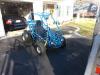
There was never any smoke (that I saw). It would just sputter and die if it came anywhere near full throttle. After I disconnected the two vents, and cleaned the spark plug, it actually runs awesome. My son had been running it almost all afternoon, and it is running great.
Here's a pic of my son on the spiderbox. 
|
|
#26
05-26-2013, 09:41 PM
|
||||
|
||||
|
that's awesome glad to see it running, I would recommend u switch to bd lifetime spindles and ball joints just to start because the stock ones are unsafe!
|
|
#27
05-26-2013, 10:00 PM
|
||||
|
||||
|
Depending on the model year, he may have the Gen 3 spindles, which are the same as the BD ones, but for sure need to get the stock ball joints out of there. Either do heims, or pony up the $$ for the Buggy Depot ball joints, and if you plan on serious riding, chop the sheet metal balljoint tabs off and weld on some 1/4" tabs before they rip off and leave someone stranded or hurt.
Pretty much what we are saying is, read what we all have done to the front end, and make your decision from there.
__________________
ASE Master and Toyota Master Diagnostic Certified Buggy Building Trainee '04 Dazon Raider 150 'modded'
|
|
#28
05-26-2013, 10:49 PM
|
|||
|
|||
|
I don't know what generation front end it is, but that is definitely the next project. The front end needs a lot ofwork, but it'll do for now.
|
|
#29
05-27-2013, 05:46 AM
|
||||
|
||||
|
I took another look at your original pics, and here is my assessment of your front end:
You have the 2nd generation spindles, which, imho, are junk You have the 'older' uneven A-arms, which limits your suspension heavily Factory ball joints need to be replaced, either heims(if you can weld) or BD bolt in set. I would go to ********, and see if they have any gen 3 spindles and 'even' type upper control arms, if not, ********** will have them in stock, but they are higher, as said before, the balljoints will eventually fail, if they haven't already, and look into beefing up the bulkhead tabs. This might sound overwhelming, but we want you and your family as safe as possible, and the front end was/is the achilles heel of yerf dog, and one of the main reasons they are not in business anymore.
__________________
ASE Master and Toyota Master Diagnostic Certified Buggy Building Trainee '04 Dazon Raider 150 'modded'
|
|
#30
05-27-2013, 08:06 AM
|
||||
|
||||
|
Glad you got it running and the boy is having a lot of fun. But do yourself a favor and make that boy wear a helmet. Those karts can, and will tip over when driven aggressively.
You can make the steering better by adding 2 more notches in the rack and pinion on either side. This greatly improves the steering radius. It can be done quite easily with some common tools, a little patience, and a steady hand.
__________________
My Yerban assault vehicle: 2.2mm stroker crank, 62mm Nikasil cyl, Taida large vavle head, American made valve springs, ported intake manifold, TM 28mm carb, stock CDI, Bando coil, TK exhaust, stock CVT except for the 14g sliders, 13/40 internal gears, 16T drive, 31T axle sprocket, 22" rear tires, and ONE BIG POTATO CANNON mounted on top..........
|
|
#31
05-27-2013, 09:48 AM
|
|||
|
|||
|
Thanks for the info on the front end guys. I will definitely be putting new ball joints and spindles on. I will most likely be replacing the upper -Arms with an even set as Masteryota advised as well.
xlint89- You said 2 more notches added to the rack and pinion will increase the steering radius (which it badly needs) I'm assuming a careful job with a hand file is the best way to go about doing this? Also, when the steering wheel is at its maximum (left or right) the outside tire is at a much greater angle. Meaning the outside tire is trying to make a tighter turn than the inside tire. I can take pics if I need to. Is this typical? is there any way to adjust this?
|
|
#32
05-27-2013, 12:24 PM
|
||||
|
||||
|
That is one of many design flaws in the front end of these yerfs, you can try adjusting your toe in a bit further out, but it isn't a real fix. The issue is lack of Ackerman angle built into the front end, and without heavy mods to the steering knuckles, its next to impossible to remedy correctly.
On the idea of cutting more teeth into the rack, I tried, and royally screwed my rack up, so be extra careful if you decide to take on that job. ********** had the upgraded racks in stock at one time, but I inquired about buying on a few months back and was told they were out and had no ETA on more. 
__________________
ASE Master and Toyota Master Diagnostic Certified Buggy Building Trainee '04 Dazon Raider 150 'modded'
|
|
#33
05-27-2013, 09:17 PM
|
||||
|
||||
|
Let me see if this will help you.
   Tools you'll need: Dremel with a cut off disk, hack saw, flat hand file, and triangle hand file. You first must grind the flat on the ends. I think I used a dremel and got pretty close with just a sanding drum. I then used a file to get it flat and even with the existing teeth. Next you have to be absolutely critical on your measurements. Use a metric ruler if you can. The "flats" on the top of the teeth are exactly 1mm. Each "valley" is exactly 5mm apart. So make 3 more marks 5, 10, and 15mm past the last tooth after you've ground the end "flat". Those 3 marks will be your new teeth. I used a hack saw to cut the new "valleys". Go slow and try to keep the blade straight. I then followed up the cut with my Dremel cut off tool to widen the notch cut. Lastly I used a "triangle" hand file to cut the angle into the tooth. That's all it took me to do it. I know it's a little fuzzy, but you can see my new tooth added in the last pic. Hope this helps
__________________
My Yerban assault vehicle: 2.2mm stroker crank, 62mm Nikasil cyl, Taida large vavle head, American made valve springs, ported intake manifold, TM 28mm carb, stock CDI, Bando coil, TK exhaust, stock CVT except for the 14g sliders, 13/40 internal gears, 16T drive, 31T axle sprocket, 22" rear tires, and ONE BIG POTATO CANNON mounted on top..........
|
|
#34
05-28-2013, 10:31 AM
|
|||
|
|||
|
That helps quite a bit! It may be a while before my son gets out of it long enough to let me do anything like that. Probably a project to do when snow is on the ground. =) Although the rainy weather hasn't been stopping him from driving it either. He came in yesterday covered in mud and a huge smile.
Some kind of fender should be my next undertaking (so says my wife)
|
|
#35
05-28-2013, 04:55 PM
|
||||
|
||||
|
lmao there will be plenty of mods ur going to want to do to the yerf
|
|
#36
06-10-2013, 02:47 PM
|
|||
|
|||
|
Another question for you knowledgeable guys.
I'm planning on welding some fenders (mudguards) onto the Spiderbox. I will disconnect the battery. Should I disconnect the other electronics too? I got the electrical stuff all nicely tucked away, and didn't want to pull it all out again unless absolutely necessary. I used to weld on my old Chevy all the time with no ill effects, but figured I'd check to see if this newer electrical system stuff was more fragile.
|
|
#37
06-10-2013, 03:03 PM
|
||||
|
||||
|
As long as you have the battery terminals off, and no chance of them arcing to the frame or battery, I think you would be ok.
__________________
ASE Master and Toyota Master Diagnostic Certified Buggy Building Trainee '04 Dazon Raider 150 'modded'
|
|
#38
06-10-2013, 03:56 PM
|
|||
|
|||
|
Wonderful - Thanks again!
|
|
#39
06-10-2013, 04:06 PM
|
||||
|
||||
|
So after reading all these post, it is awesome to hear you got the buggy up and running.
Enjoy...
__________________
Growing old is mandatory  Growing up is optional https://www.youtube.com/watch?v=NEXoa-8d7qE
|
|
#40
06-10-2013, 05:52 PM
|
||||
|
||||
|
just disconnect the battery and ur fine
|
|
|
|