

|
|
|
|||||||
| Electrical Tech General Tech for Electrical issues not related to specific engines (Lights etc) |

 |
|
|
Thread Tools |
|
#1
 02-04-2012, 01:43 PM
|
|||
|
|||
|
Situation:
I have the two front lights removed from this buggy; the bulbs 'appear' visually to be bad, and I could get neither of them to function by wiring direct to the light assembly wiring plugs from a 12V battery. I get no voltage with a 12V test light at the wiring harness on the buggy with the engine not running - light switch on or off. However, with the engine running, I get a 12V response from the light harness plugs with the light switch both on and off [?]. The bulbs in the front light housings are unlike any I have ever seen; I cannot readily/easily pull them out. It looks like they are integral to a round, metal disk that is bolted to the assembly. I removed and tested the rear light bulb with a 12V battery and it lights up brightly. It looks very similar to a brake/back up light bulb in GM vehicles. I will test it on the vehicle with the engine running later today. Questions: Are light bulbs for these front lights available at auto parts outlets? Shouldn't the light switch stop the front lights harness plugs from getting voltage when it is in the off position, engine running? How can I test the stop light switch on the master cylinder to see if it is functioning? If the brake light doesn't work when tested, where do I start testing for voltage - at the master cylinder switch, or at the brake light end of the circuit? Summary: Front light bulbs don't work. I do get 12V at the light harness plugs on the buggy, only with the engine running, regardless of where the light switch is set. The horn doesn't work either; but, if they can't see me coming in the dark, they probably couldn't hear me either. I'll never drive the buggy at night, so lights are not a necessity for me. Since I have no place to ride it anyway, I'll let the next owner inherit the lights situation. Thanks for any comments; I have read everything in the forum about lights and lighting systems, but it is mostly way over my head regarding stators, AC/DC, 6 - 8 - 11 poles, engine running vs not running, etc. 
|
|
#2
02-04-2012, 07:06 PM
|
||||
|
||||
|
If you have a test light- unplug one of the wires @ the master, hook the test light to the end of the disconnected wire and the master terminal- press brakes- it should light up if working properly. Testing the front lights works the same, is the light switch 2 pole/terminal or 3?
Can you post a pic of the bulbs?
|
|
#3
02-04-2012, 09:02 PM
|
|||
|
|||
|
I tested the brake light switch at the master cylinder; first, with an ohmmeter and the engine not running, and it showed it as working when the pedal is pushed. Then, with the engine running, I used a 12V test light and probed the two wire connectors on the switch. I got voltage at one of the terminals, then at both when I pressed the brake pedal. I had earlier tested the brake light bulb and it works, so I think the problem is between the switch and the brake light bulb. I haven't checked for voltage at the brake light end yet.
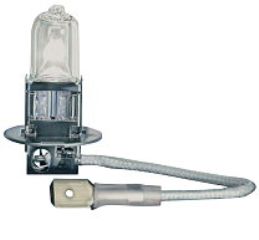
Both the front light wire harnesses activate the test light on the green wire at the plug with the engine running. I did not use a voltmeter, just a test light, on all the tests so far. Pics of the front light bulb type.
|
|
#4
02-04-2012, 10:14 PM
|
||||
|
||||
|
The front light bulb appears to be a standard wedge type- wiggle it somemore and see if it will pull out. Any auto parts store should have this- I buy them @ Lowes!!
Your lights aren't going to be very bright when you get them to work unfortunately as these bulbs are usually low wattage (ususally brake or indicator lights) Since your test showed the sending unit is good then it's somewhere in the wiring- check for a good ground on the light fixture itself.
|
|
#5
02-05-2012, 01:50 PM
|
|||
|
|||
|
I can find absolutely no way to remove those bulbs from this kind of receptacle. Since they are obviously burned out, I am thinking of crushing one of them and see if I can determine how they are attached. I bent up 4 little metal tabs, two on each side, to see if they were somehow holding the bulb. No go, no effect. I unscrewed the screw holding the green wire to the mounting frame of the light; the white(ish), cloth like covered wire goes into the side of the bottom of the fitting, and I can not see how it is attached, nor how it would be isolated from the metal of the frame to avoid shorting out. There is a very slight, emphasis - slight - movement of the bulb side to side, but no movement up or down. Surely, I'm missing something simple and obvious. Again.
|
|
#6
02-05-2012, 02:13 PM
|
||||
|
||||
|
Those pic's tell a different story as I can see they're not removable from the socket. No idea where to get them.
|
|
#7
02-05-2012, 02:21 PM
|
||||
|
||||
|
I have gotten those at our oriellys auto parts store in the
fog lights area they had 2 sizes think 25 and 50 watt I can't remember for sure the sizes but that's were I got that style bulb
|
|
#8
02-05-2012, 07:16 PM
|
||||
|
||||
|
Those are HID style bulbs. They come with the circular base as a unit. The unit is held in place with the sheet metal screw. replacements can be found at any auto parts store. Just make sure the replacements are the same wattage. unplug the wire connection, loosen the screw to remove, reverse to install fresh bulb
|
|
#9
02-05-2012, 08:36 PM
|
|||
|
|||
|
Thanks, ckau. I had already tried to do that. The round metal disk that the bulb is mounted into will not pass through the smaller, square hole in the light assembly frame. The other possibility is that if the white wire could be removed from the base of the bulb frame, then the bulb/disk could be removed and replaced. Unfortunately, I cannot remove the white wire. Under a magnifying glass, it appears that the wiring that protrudes from the end of the wire is actually soldered (?) to some little metal protrusion coming out of the bottom of the bulb. I know this just can't be, but it looks like the entire headlight assembly has to be replaced as a complete unit.
|
|
#10
02-05-2012, 11:43 PM
|
||||
|
||||
|
The bulbs are standard H3 halogen bulbs. Most auto stores will not have anything bellow 55w and yours are either 15w or 35w. The white lead is the hot side of the bulb (not removable) and the round base is ground.
I've upgraded most of mine with LED replacements and have spare new LED or used low wattage H3 bulbs available. Send me a PM if your search fails to find replacements.
|
|
#11
02-06-2012, 11:33 AM
|
|||
|
|||
|
Thank you GX150 for the information. If I could find those kind of bulbs, would I have to cut the original white/hot wire and splice the new one to it? I'll try to e-mail you later regarding your available ones and how to install/replace mine.
|
|
#12
02-06-2012, 11:57 AM
|
||||
|
||||
|
If you follow the white wire from the bulb, it should terminate in an automotive male spade lug - The female side of the plug will be your chassis wiring. Once you remove the small cross head screw holding the green ground wire, the H3 bulb should slip free of the metal tab and pull free from the light reflector/housing.
Last edited by GX150; 02-06-2012 at 12:00 PM.
|
|
#13
02-06-2012, 12:23 PM
|
|||
|
|||
|
This particular setup has both the green and white wires going out of the light housing and reflector through a solid plastic tube to a plastic connector. I can probably get the white wire out of that connector, but would have to replace the male plug on the new bulb with another one that will fit the chassis connector. Is that feasible, and correct?
|
|
#14
02-06-2012, 12:45 PM
|
||||
|
||||
|
If there is not a spade behind the reflector, that is the worst design I have seen. The white wire off the bulb is one piece all the way to the external plastic connector?
Replace those lights with Harbor Freight specials if the bulbs are hard wired. You will save yourself aggravation next time a bulb fails.
|
|
#15
02-06-2012, 01:06 PM
|
|||
|
|||
|
Yes, the white wire is one solid piece all the way from the bottom of the bulb to the external connector. I agree with the efficiency of the design. I could of course just cut the existing white wire, leaving enough on the harness side of the cut to splice it to the new bulb/spade end.
First, to look for new bulbs of this type and do a splice job; if no results, get some like yours and splice into the harness. If no luck with this, look for completely new light assemblies, that might be of a size to bolt onto the existing light brackets. Thank you for your patience with me, and for all the info.
|
|
#16
02-08-2012, 12:22 PM
|
|||
|
|||
|
I bought a couple of the suggested bulbs, with the male spade white wire connector. Before I splice them into the buggy harness/connector, is there anything I should consider to avoid blowing them out? I got the 35 watt bulbs to replace the 15W's in the buggy. I do plan to check out the light switch first, since on a previous test with the engine running, I got voltage at the harness connectors with the switch both on and off. I'm going to repeat that test with a voltmeter instead of the test light.
Any warnings, precautions, concerns, possible problems, etc.?
|
|
#17
02-08-2012, 12:32 PM
|
||||
|
||||
|
The only way you'd blow the bulbs is if you have too much voltage- when a bulb is rated @ 12v it means it runs perfectly at that voltage for the advertised life limit. I'd think voltage above 16-17v would cause premature failure. If your stator or voltage regulator is allowing that- you have a much greater issue!!!!
|
|
#18
02-08-2012, 05:28 PM
|
|||
|
|||
|
Thanks for the guidance, metalstudman1, I understand about the voltage maximums.
I just retested everything, with both a 12V test light and a voltmeter. Even though the lights, and horn, connectors light up the test light with the engine running, the voltmeter shows no voltage at all at the same connections. This confuses me, since I thought that if the test light glows, there was voltage there. I had previously done some repair work on the damaged main ground wire and a same color smaller wire that go into and out of the rectangular black box that holds much of the electronic components of the machine. I did not notice, but was not looking for, any type of fuse holder in that box. If there is a fuse for the lighting system in this machine, that probably is the root of my problems. I hate to have to cut all the tie wraps that are holding the black box together and to the frame, but would gladly do so if I knew there was a fuse in there somewhere. The snaps that hold the lid onto the base of that box were broken, as was the weld holding the base to the frame; the previous owner had duct taped it all together. Is it possible/probable that there is a fuse in this machine for the lights?
|
|
#19
02-08-2012, 07:22 PM
|
||||
|
||||
|
There usually is a main fuse, from what I've seen they almost always near the battery terminal going out to the ignition. Most lights that come with a fuse are after the switch. It's possible there could be a fuse in your box-But if the fuse was blown your test light wouldn't work on the lighting circuit!!!, something with your volt meter isn't working properly (not grounded or on the wrong setting or leads in the wrong outlets) When you test the battery with your volt meter does it show 12+ volts DC?
|
|
#21
02-09-2012, 06:54 AM
|
||||
|
||||
|
ditto the above, you could be reading charging voltage and getting the test light bulb lit with just 1-2 volts --and if the multimeter is set on too high of a voltage range, you'd read little or nothing. Cutting a few tie wraps to check for a fuse would be a good idea at this stage.
|
|
#22
02-09-2012, 02:39 PM
|
|||
|
|||
|
metalstudman1, GX150 and x-bird: I really appreciate your patience and willingness to help me.
By double checking my two voltmeters and trying both of them, I am able to get a voltage reading at the two headlight buggy harness plugs with the engine running. They only reads from 8.48 to 8.51 volts, with both meters. I tried to temporarily hook up one of the new bulbs to the harness but got no lighting results, maybe due to the lower voltage there? The new bulb is bright when hooked directly to the buggy battery. I removed all the tie wraps holding the black box together and to the frame members. There is a 10 amp inline fuse/holder in there, with small red wires going in and out. The fuse is good; with it removed, nothing happens when I turn on the ignition switch; with it installed, the engine starts and runs normally. When I cranked the engine to check that fuse, I soon noticed that the corner of the base of the black box (where it had at one time been welded to the frame) was vibrating against the side of the engine case, and sparking when it touched that case. With my jury rigged attaching system, i.e. tie wraps, should that metal base of the box be connected to the frame? The engine ran normally, and I noticed no effects when that sparking occurred. I also found when doing all this, that the ground cable connection at the battery was loose. I tightened it and cranked the engine again, but have not gone back yet to re-check the voltage elsewhere. How do I verify my ground wires? Use a resistance setting? Where to where? Isn't this fun? Thanks again gentlemen for your help.
|
|
#23
02-09-2012, 03:36 PM
|
||||
|
||||
|
Your ground is the issue and it's as important as the positive (hot) wire to make everything work correctly. To check a ground(any wire) is a simple ohm's check at both ends to see if you have continiuty ( basically any ohm setting should show a value).You need to have a ground from the battery to the frame or swingarm, cockpit frame to swingarm, swingarm to engine. Most of the time the ground wire should be a heavier gauge wire than the wiring harmess. When grounding the wires try to find a bolt that doesn't have a moveable part attached and has a constant metal path to the next electrical connection. I fastened my grounds with self drilling hex screws and make sure the connector has some bare metal to rest on.
Your lights will work at that voltage- IMO I'd just wire the lights straight to the battery with a fuse and be done with it, this way you get 12v constant and they won't dim at idle, your switch makes you the decision maker not the stator/voltage regulator!! Testing your switch is the same process as checking your ground, if the switch is questionable -replace it!! a bad switch could short out something more serious. Last edited by metalstudman1; 02-09-2012 at 09:23 PM.
|
|
#24
02-09-2012, 09:04 PM
|
|||
|
|||
|
Latest efforts: I could find no wires grounding/connection the frame to swingarm to engine, etc. But, using an ohmmeter, there is continuity between any two of the items and between all three. There is also continuity between the base of the black box metal frame and the chassis frame, even though they are not welded together.
Lights: with the engine running, I get about 8.5 V at the green wire from the chassis harness light connectors. However, the green wires from the connectors are the ones that are screwed onto the round metal base of the new light bulbs. I thought it would be the opposite, that the metal base would be the ground wire. I haven't been up to trying to remove the little light and horn switches from the dash and testing them yet. I guess I'll try to splice the white wires from the new light bulbs to the white wires in the harness connectors, then screw the green wire terminals to the bulb bases and see if they light up when I crank the engine. Then I have to try and figure why the rear light doesn't work, nor does the brake filament in that bulb. That fixture does have a three wire connection, while the front lights have two wire connectors. I'm sure it's something simple, but there's a simpleton trying to solve it. Thanks again for all the help.
|
|
#25
02-15-2012, 08:52 AM
|
||||
|
||||
|
if the case is sparking when touching the frame, i think there's a chance of a positive wire shorting out inside the case or against the frame somewhere. In theory, if the instrument panel up front is correctly connected to the frame (grounded by fasteners) and a negative wire runs from it to the engine panel and that's grounded, then the ground circuit would be complete. Given the state of yours, i'd add a ground strap or wire from the rear swingarm to the front frame.
My instrument panel is not connected at the moment and i had dead lights until i realized that the ground circuit was not carried anywhere else from front to rear. as soon as i grounded the battery to the front frame, i had lights. Even though when i connect everything properly i know i'll have a good ground, i still am going to add a strap from the rear to the front. as far as the rear light goes, i think the 3 wires = ground, 12v on/running (dim), 12v brake on (bright) Last edited by x-bird; 02-15-2012 at 08:55 AM.
|
|
#26
02-15-2012, 11:07 AM
|
|||
|
|||
|
Thank you, x-bird. My instrument panel attaches with four bolts, two bolts directly into the frame member(s) and two with bolts and nuts through the panel.
I have been trying to find any possible hot wire grounding to the electronic box, and have some problems seeing any such grounding/wire damage in that mass of wiring. The green/ground wires from the two front light harness plugs show continuity to the multiple green wire bundle in the 'black' box (which by the way was not taped or otherwise protected; just several small green wires soldered together). I still get about 8.5 volts at those green wires where the two front lights plug in, when the engine is running. I get no voltage through the whitish/creamy colored wires in the lights plugs. It looks like the rear light fixture is grounded properly through the harness, with both high and low/dim and bright connectors showing continuity to ground. As soon as I can get some help, I plan to go into the wiring routing from front/lights to rear of the buggy, hoping to find a problem - also to find where those wired are plugged/connected to the rest of the harness at the black box. I'm sure (?) I need to unplug those circuits at both ends to isolate them and check for grounding of the white/power wires. Nothing I have done so far has any effect on the functioning of the engine; it cranks immediately, idles well and accelerates pretty well, sitting in the shop in neutral. I have major problems understanding vehicle electricity and the terms used to describe functions and problems, and that contributes to my problem. Thank you for your continuing help. I need it.
|
|
#27
02-15-2012, 12:54 PM
|
||||
|
||||
|
I'm not much better and i took 2 years of vo-tech electrical classes in the afternoons during high school. )) Try this ... set your meter and leads to the audible continuity setting, connect one lead to the positive and the other to the frame, in this instance i'd start with the rear swingarm, then cycle all your switches. If you get an audible tone when turning a switch to the on position, then that circuit has a short to ground in it somewhere. I accidentally hooked my black wire to the ground connector on the aux. power plug in my panel, and put the green on the positive connection. The engine ran fine, i didn't realize black was hot until my reverse cable hit the instrument panel and sparked. I think they consulted with Lucas on wiring these up .... ))) oh dang, i let my smoke out again ....
|
|
#28
02-16-2012, 11:37 AM
|
|||
|
|||
|
x-bird, I don't have an 'audible' type volt/ohmmeter. Using the ohmmeter function (?), do I connect one lead to positive (+ terminal on the battery?) and the other lead to the frame/ground to check the switches as you describe?
|
|
#30
02-17-2012, 08:56 PM
|
|||
|
|||
|
Well, I definitely got continuity! I thought the needle of the ohmmeter would break off when I touched the second lead to the swingarm mounting nut/bolt. Normally, when I get contact/continuity, the needle swings toward 0 at an acceptable speed, but this really took off - it was instantaneous and fast!
I tried some other continuity tests on wires in the front to rear wiring bundle that goes through the passenger side frame tube. At the front end of this bundle, wires separate out of the flexible covering and go to: each of the front light plugs, the brake light switch, and a bunch more to the instrument panel components. I unplugged the 9 pin plug at the rear of the machine where it plugs into the harness from the black box, so this harness is now isolated. Checking the green/ground wire from the light plug(s) first, I got no continuity from the front to the rear. Same for the white(ish) light plug wire. I did get continuity from the front end light plug green/ground wire to the black w/white stripe wire at the rear plug of this harness; that wire goes from the rear plug to the kill switch on the panel. I'm at a loss to understand all this. If I get no continuity in that green wire from front to rear of this harness, how can I get voltage through it when the engine is running and the harness is plugged in?
|
|
|
|