
|
|
|
|||||||
| FrankenBuggy Tech Unconventional and Home Built Buggy Tech Forum |

 |
|
|
Thread Tools |
|
#1
 04-17-2012, 04:33 PM
|
||||
|
||||
|
Dismantled most of the '85 250 Suzuki quadrunner the other day and took the reciprocating saw to its frame yesterday.
 Need to finish a few rockhound bits (heims come in tomorrow for the steering arms) Then build a quick shed-roof parking "garage" for it and the mini shark using the backside of my 6-foot driveway fence as a back wall. After that, the Sunl and Suzy parts take up residence in the garage for reassembly. I've already scarfed the seat and reverse lever from the Sunl, so it needs those and rear tires. The X-bird avalanche of pics to come shortly ..... 
|
|
#2
05-30-2012, 06:49 AM
|
||||
|
||||
|
So the S-thing has taken up residence in the garage. Now have 3 buggies and two cars crammed in there!
Hit the recycling yard yesterday for some parts picking and brought home a Polaris that I may use for it instead of the Suzuki. suzuki method would be a straight cut down the middle of the suzuki frame and welding either side to the side of the front end of the Sunl. That will require a complete redesign of the steering layout. The polaris method would be to use the polaris struts and lower arms, alignment to the stock steering would be pretty close. Since the lower arms are much longer than the Sunl's, the strut top position would need to be lower and kicked outward more. (this would put the droop where i want it and add a lot of clearance) 1 strut tube has a big ding in it up top, so it will need a replacement. Polaris is a 2wd with and F-N-R gearbox still on it. There's another, exact same model with engine sitting atop their heap. My "guy in the yard" has been holding it for another guy for 2 months now. The sunl was rolled, rear main cross bar has a bit of a bend to it at the end--nothing that will give any issues. It's a pretty solid unit. rear axle is straight and very good quality, and the swingarm is really stout. If i could find another of these rear ends, i'd use it for the rockhound. The main frame also has a second swingarm mount hole down lower that will add more clearance. going to go with that position. Last edited by x-bird; 05-30-2012 at 06:54 AM.
|
|
#4
05-30-2012, 11:04 PM
|
||||
|
||||
|
I still don't know what model your Polaris is even after seeing the pic!!!! Haven't seen that type tranny. good luck with your new choices!
|
|
#5
05-31-2012, 07:15 AM
|
||||
|
||||
|
did a little digging. No ID anywhere on it except for vin/serial # on the frame. Looks like it's a 1985 era 250 Trailboss. I'd say its one of the first years because of the large Macpherson strut sticker on the front bumper.
I'm 95 percent sold on doing the polaris front, but i have to find new struts for it. Looks like $150 for a pair is the price range, but finding something that fits may be an issue. Either way i need front shocks for anything i do with this, so this particular expense doesn't factor into the decision too much except for availability.
|
|
#6
08-10-2012, 05:29 PM
|
||||
|
||||
|
And the remaining 5 percent Suzuki won me over. Rather than invest in new struts I found a way to make the quadrunner front end work better.
In stock form, the a-arms on it have very little droop and the ball joints limit any further droop because of bind relative to their position in the a-arm. I've been staring at this thing off and on for weeks. Today i took the penetrating oil to it, loosened it all up and tested its travel. I've found that if i cut the lower ball joint's mount tube out and reposition in to a more upward angle I can get about a 6 inch droop out of it and increase it's travel range. More droop if i cut some out of the bottom box frame where the lower arm mounts. I intend to mount this way out front, about half the a-arm will be in thin air so to speak until i add tubing to tie it all it. This will give me room beyond the pedals to drop the steering rack down into and be inline at the same height with the QR's steering arms. I'll just extend the column with one of the yerf 2x jointed telescopic deals. This would add about 1 foot to the wheelbase and put the front track anywhere from 52 to 56--haven't checked the rim offset yet. Clearance, it will pick up around 4 inches up front and add about 3 inches more travel.
|
|
#7
10-22-2012, 11:11 PM
|
||||
|
||||
|
Been way to busy with work to do much more with this other than think up possible modifications. Rummaged around the scrap heap tonight and pulled the oddball rear axle assembly i had buried in it and dragged it into the garage. Took awhile but i finally found that it's the rear out of a kawasaki Bayou. No parts numbers or ID anywhere on it, so i can't tell the year or exact model 220 or 300, likely late 80s early 90s. Weird setup with a single large brake drum/hub on one side and plain hub on the other. Not sure if it's supposed to, but it acts like an open differential. input ratio is one driveshaft rev = about 1/4 turn of the wheel, so if i couple this to the 250 i can go 1:1 into the jackshaft and have real creeper low gears.
Down side is that it's narrow at around 35 inches at the outside of the hubs. that could be addressed with rim offsets and spacers. Up side is a that i could mount the 250 sideways to the main frame, run a combination jackshaft/driveshaft and set this up as a four-link coil-over rear.
|
|
#9
10-02-2014, 08:36 PM
|
||||
|
||||
|
Well, nearly 2 years later, this pile of old metal dragged itself back into the garage begging to be put out of it's misery or resurrected ...
Since the rockhound is fixed and not going to see any work until a money tree grows in the backyard, I figured it was high time to make something new. I have pretty much everything to complete the build in one run. "All I need is ... this chair and ... " Lacking a seat and harnesses, and front hubs or rims may give me some fits. Have to make a reverse cable end cap since i sent that off with the last gy6. Pretty much looking like it's going to fit together pretty well. Silver lines are tubes getting cut out (already done plus more sawzall fun) and red is replacements or revisions.
|
|
#11
10-03-2014, 12:21 PM
|
||||
|
||||
|
We know this one will be awesome too.
If I were closer I would X...
__________________
Growing old is mandatory  Growing up is optional  https://www.youtube.com/watch?v=NEXoa-8d7qE
|
|
#12
10-08-2014, 07:50 PM
|
||||
|
||||
|
Got a little over 2 full days into it now hours-wise. Rear framework is ready to weld up. the back frame extension will have a piece of angle iron over the rear most tube to mount the heim tabs for the subframe connection and to close off the end of the side tube.
Cut off everything but the reverse lever mount, utility rack tabs and the steering column mount hoop --which may get moved anyway along with the main bar its on. A bit of misc. tight spot paint removal to do. Started in on blending the quad front end into the picture today, that's working out fairly well. first side is tedious as i'm slowly grinding away at about 5 different points to fit it in correctly. Side 2 will be a lot quicker as i'll know how much excess to take off right at the start.
|
|
#13
10-08-2014, 08:11 PM
|
||||
|
||||
|
Today's front end session results. Front view ---Still have to move it inward up top (need to get the original quad A-arm frame piece vertical.)
Side view ---It needs rotated a bit more counter clockwise within the sunl frame to take a couple degrees of added caster out. All the tubes were ground over and over to get to this point. Probably 3-4 more grinding/fitting sessions to go. If you have an air disc grinder that you don't use in favor of a 4 1/2 in. electric angle grinder, here's the best $12.00 you can spend -- if you've pack-ratted your old discs. I've always taken my bigger grinder discs and successively cut them down for re-use. My compressor though is a very loud oil-less so i use it very little for fab work. This just saved me a bunch of money since i have piles of 5 in discs with worn out edges. Sears hardware "4 1/2 angle grinder conversion kit" comes with 2 50-grit discs which didn't last too long as they were noticeably thinner than all of my old ones. 
Last edited by x-bird; 10-08-2014 at 08:17 PM.
|
|
#14
10-14-2014, 11:02 PM
|
||||
|
||||
|
Had some "fun" to deal with ... must've been a Friday shift that built this buggy! After setting the left front up, I matched the cuts and grinds on the right to it. ... Only to find that the curved main front tube on the Sunl is mounted further inboard on the right side and the angled "vertical: tube is mounted farther forward.
To keep the front and rear track on center and square is requiring what would appear to be offset installation of the quad frame parts. pictures show the difference. To make it look somewhat decent, i had to ditch the idea of blending the tubing from the quad into the Sunl frame (basically cut off and threw away several hours of grinder finessing) and am using plate and gussets to tie it together an make it look somewhat even. to tie the huge gap into the frame, I resorted to welding in a piece of 3/4" square tube (once again it's old Yerf parts to the rescue --a chunk of seat mount tube  ) alongside the curved sunl tube that I can tie the quad frame solidly to. It'll be hidden by a piece of triangular plate front and rear. ) alongside the curved sunl tube that I can tie the quad frame solidly to. It'll be hidden by a piece of triangular plate front and rear.
|
|
#15
11-04-2014, 11:18 PM
|
||||
|
||||
|
Lost a couple weeks to work projects and no energy/time ...
Back at it, neighbor gave me a porsche 924 seat in really nice shape, took a bit of rearranging of the rear frame to make it fit ... Tilt forward will make it nice for getting at the valve cover, battery and exhaust pipe. Also has recline and a pretty long range slider set. Fwiw, it's only 18.5" wide at the base, which is narrower than most buggy/race seats unless you get into aluminum pieces like Kirkey etc. Also picked up a used 5-point RJS set for $35 inc. shipping. Even though they're older than mine, i may swap my set out for these since they have the chest latch and a narrower anti-sub belt. Managed to get the right side of the quad frame tacked on tonight. took a lot of triangulation checking off the centerline and rear corners to make sure that both sides are square. Next on the list is a bunch of mount tabs for the rear swingarm and shocks, setting up the rack and upper shock mounts.
|
|
#16
11-13-2014, 07:46 PM
|
||||
|
||||
|
Got the cage framework done. Hated the look of the original with it's single angled-out front and rear cross bar and nothing at all overhead. Goofy looking and unsafe.
Didn't want a series of straight cross tubes, otherwise the whole thing would look like a bent up ladder. Cut the angles off one cross bar and ran it across the front, added another straight tube at the rear and used the other angled cross bar to go down the center. Gave it a bit of support and a better look with a couple tubing leftovers from a work project. Up front i may cut off the bent tube at the center and give it an arrow point treatment to match the top. Also added the seat support tubes to the bottom, of course none of the originals matched where i need to mount the seat. Swingarm mounts are also finished. Used a piece of light angle iron across the back to provide a flat surface and added meat to the rear tube. Rear shocks land right on the primary tube junction. I'll likely make a high and low mount point. Last edited by x-bird; 11-13-2014 at 07:50 PM.
|
|
#17
11-19-2014, 05:03 PM
|
||||
|
||||
|
Got the seat in, I think i may tweak the back part of the cage roof (inverted "T" area) as head clearance with the seat all the way back is a little close (about 3 inches). Also made and installed the rear shock mounts. Got lucky and made a major score so I'll be able to take the rockhound's podiums for this and don't need to rebuild a backup pair of podiums.
Sacrificed a work day (meh, it was too flippin cold to dig and set some footers) and made some "boxes" to convert the quadrunner front end over to heim joints. Got the first side done. At the moment, final product looks rough, but they'll get shaped--lower already is done and looks much nicer. My buddy at HPVE is making some 22mm OD threaded bungs for the heims--they fit into the tube where the ball joints were. Can't get the 22mm OD and 12mm x 1.25 anywhere unless i start stealing and cutting up everyone's yerf steering rack shafts (ironically, they're perfect) Almost scored some with Travis at BD, from when they setup the fixtures to redo the yerf racks with the extra teeth (I may have to get me one of those, because my handmade deal is getting pretty sloppy) but he couldn't find the remains of the racks they sacrificed. Once i get the bungs and hi misalignment inserts (free from Steinjager from my contest entry)  I'll be able to setup the heim position then the front shock mounts. I'll be able to setup the heim position then the front shock mounts.
|
|
#18
12-02-2014, 06:24 PM
|
||||
|
||||
|
Going for the "pre-christmas park it for sale finish" glimmer of hope of getting her done ...
The last twelve days (or so) of the Sunlzuki book continues .... Front end has been a real finicky SOB, with the frame tubing installed unequally side-to-side, taking measurements to keep the front and rear square is down to only using the rear swingarm mount tube i added, the centerline marks down the frame, and the quad a-arm frames. Worse yet, when i add things, they actually have to go in a tad crooked in relation to the original frame here and there to keep the front and rear square ... bit of a headache.  understatement... understatement... Anywho, went to prep the left a-arms and the last ball joint proved to be the typical cussing and BFH match. The arm had already been bent/twisted and the lowers needed the ball joint tubes re-angled for the heim bungs to avoid bind at the droop I'm putting them at, so the 5-pound sledge came out, as did the ball joint, but not without more damage to the arm. So I rebuilt the things. With one new lower made up, i went ahead and futzed around long enough to get the rack in position. I'm using leftover heims that i had from the first yerf steering rack/tie rod design, some free-but-for-$0.08-shipping hi-misaligment spacers and some close-but-not-quite-right threaded tube to temporarily put the front spindle and hub on the a-arms. Sort of a 6-handed deal to do. Nothings welded and nothing threads in... yet ... Waiting for my buddy to finish the heim bungs. With the spindle and hubs together and loosely hanging on the arms, i got the rack set and came up with a plan for the steering column. Going to make it length adjustable using 1" tube, the original steering shaft, and a golf cart tie rod. The 1" and tie rod get small holes through both and a pair of grade 8 thru bolts. It will be height adjustable by having a tube through the mounting block with nuts welded in the ends. By slightly rotating the rack, the height can be set with the thru tube hung between a pair of plates with holes drilled on a matching arc. I needed tires and rims, so when a local used atv shop failed to have a match for the quad's 9" 4 x 130 pattern rim (real oddball) I grabbed a royally abused pair of rims with decent tires for $20. plus the front plastic from the '85 trailboss. The cleaned-up rim was the worst of the pair, nice light aluminum ones, but it took about 3 hours of hammer and dolly work to make it presentable. if it proves to be noticeably wobbly, i may have to redrill the polaris trailboss rims with the jig i made to do these. Seat mounts are in, 5 point harness mounts are in, rear shock mounts are in. I gotta do battery tray, steering and finish up the other a-arm and heim adapters. After that it's front shock mounts, maybe lights, wiring and paint time. Ohhhhhh and brakes ... 
|
|
#19
02-13-2015, 07:02 AM
|
||||
|
||||
|
Didn't realize so much time had passed since I updated ... lets see .... those front rims didn't work out, couldn't get rid of a through-both-sides bend in the bad one, so i had to revert to a set of 19 inch tires on steel rims. used the same method to locate the new holes.
Roughed everything together, got a test ride in (no video) Finished up all the frame work and got the floor in earlier this week. Painted the frame yesterday, going to clearcoat it today, then it's reassembly time ...
|
|
#20
02-16-2015, 09:40 PM
|
||||
|
||||
|
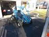
In paint and starting to go back together. Caulked the floor tubes in all the way around. bit of a pain, but well worth it imo. have a little touch up to do on the rear swingarm, paint the rear rims and pick up some assorted nuts n bolts ...
|
|
#21
02-21-2015, 12:58 PM
|
||||
|
||||
|
Really sweet job. Love those rear fenders. Is it possible to explain and or show close up of the electronic box rear cover ? Looks larger than stock and more user friendly than the cramped version.
|
|
#22
02-21-2015, 03:41 PM
|
||||
|
||||
|
Quote:
The fenders are my spares for the rockhound, really didn't want to use them up, but this frame was begging for them. They're the top cover of PING golf club sales display racks where the club grip goes in at the base. I closed my golf pro shop a few years ago and stripped the racks for any metal on them--turns out they make great fenders, you just have to plug the holes with something. In this case a strip of steel painted blue with nuts welded to it. If the holes start getting too much dirt, the strips can be unbolted and cleaned or repainted. Pro shops get these for free, if you like them, start checking in at golf courses, Dicks sporting goods etc., chances are they have plenty gathering dust in the back that they'd part with. Buggy electrical systems and my treatment of them are kind of a long standing joke with me. I usually just zip tyies all the bits to the closest tube and call it done LOL ...  For this one i had to actually make something a little better. Box is just a piece of 3/16ths aluminum that had been the back wall of some industrial type machine. I picked up 4 identical pieces at the scrap yard, roughly 2'x2' a few years back for about $3.00 each. Pretty much used some up at work and some on the buggies, this was my last sizable chunk. They had a lot of holes and slots for cooling. Took a section of one, bent it in a shallow "U" then bolted 2 90* "L"s to the other sides. On the top frame of the buggy i welded a tab for either end of the box to bolt to with a little gap so it doesn't rattle on the frame. Inside, a chunk of the original (original to an old Carter Talon i believe) CDI and starter coil mount bracket is bolted to the floor of the box. The regulator gets bolted to the back outside of the box for cooling. the cover is just sheet metal bent in a "U" with 4 holes and U-nuts on the aluminum box sides. It's not weatherproof, there's about 3/4" gap under the cover for the wire looms to pass through front and rear. I had over 2 foot of extra wiring length that I cut out of the harness, even after that I think it's going to be a bit tight, but definitely better than the stockers. I'll get some pics later tonight ... Last edited by x-bird; 02-21-2015 at 03:48 PM.
|
|
#24
02-23-2015, 11:04 PM
|
||||
|
||||
|
Nothing better than repurposing .. until you use fresh tube, angle and plate, then you realize how much clean up work going with used stuff takes.
really hoped this would be a quick flipper, but I get too bogged down trying to make it as good as i'd want it for myself. matter of fact it then turns out better than i'd do for myself because i'll live with some dirty and grimy bits and pieces and multi-color parts spray-bombed dirty on the fly to keep the rust off. Pics of the electric box, very basic. Spent way more time on the wiring than i ever have before. there's a bolt for the grounds to all tap together on in the box. Got rid of that crimped spider connector mess in the harness and made them all individual terminal ends to the lug. They lead to the coil mount, a short heavy jump from there to the engine and another goes to the battery. the battery has a separate heavy ground to the main frame (not connected yet in the picture). There's actually nothing that ties a ground to the main chassis, but if someone in the future goes to ground to the frame, it''ll work. Harness straps are allen bolted to 5/16th-18 U-nuts with one leg of the U snapped off and welded to the frame. real easy way to tab for wiring, cables and body panels. I have to re-do the bundle under the dash, it has the relay and connectors in it, wrapped with padded and velcro closure inserts from my soft carrying case from my rechargable drill. the wrap adds too much bulk and takes away the upper 3 steering mount holes. picked up some double-sided velcro straps today to replace the padding with. hopefully it will give more room and still look decent. it's really tight behind the panels. Last edited by x-bird; 02-23-2015 at 11:09 PM.
|
|
#25
02-24-2015, 03:26 PM
|
||||
|
||||
|
pretty cool build xbird
__________________
Hammer head Single seater know as herbie under construction Aluminum fuel tank, aluminum wheels, custom fuel/cargo rack, entire rewire, trail tech vapor, ported big valve head, a12camshaft, 12 gram sliders, straight intake, kirkey wide seat, front end extension. 4 point harness, welded cage. Hammerhead exhaust. Blade Single Seater Restore welded cage, engine build, new wiring harness/electric box, spun aluminum fuel tank.
|
|
#26
02-24-2015, 03:52 PM
|
||||
|
||||
|
Getting down to it. Just dropped the rear axle. forgot how easy i made it. pull the tires, loosen and pop the chain, undo 10 bolts. Going to clean and repaint it, change the translucent red center section to blue and slot the Dana cover for the chain like I always intended--if i can find it in the metal pile. LOL, I know i didn't scrap it.
|
|
#29
03-03-2015, 06:49 PM
|
||||
|
||||
|
pretty cool and unique buggy.
__________________
Hammer head Single seater know as herbie under construction Aluminum fuel tank, aluminum wheels, custom fuel/cargo rack, entire rewire, trail tech vapor, ported big valve head, a12camshaft, 12 gram sliders, straight intake, kirkey wide seat, front end extension. 4 point harness, welded cage. Hammerhead exhaust. Blade Single Seater Restore welded cage, engine build, new wiring harness/electric box, spun aluminum fuel tank.
|
|
#33
03-04-2015, 07:59 PM
|
||||
|
||||
|
Thanks for the comments, couldn't have done something like this without the knowledge I've gained here from all you buggy nuts!
Took it out for pics today. No way to test ride and video it with the snow and slop depth we have here. Fires on the first crank, pulls really good and strong off the line. I test rode it before paint (and when there was no snow on the ground) and all is gtg, just would like a video for the ad and posterity's sake LOL ... Put as much detail and anal-retentiveness into this one as I did my daughter's. I'm going to shoot for the moon (2k) and settle for what I expect. Will it cover the labor---no, restoration projects rarely do. Around here people ask stupid money for junk, so i may hit the mark. Heck, I got 1100. for the baja and that was nowhere as nice nor did it have the quality of this one. Still have a couple tiny bits to finish, but nothing I can't knock out quickly if a buyer calls. Feedback welcome on my cl ad  http://allentown.craigslist.org/snw/4917712615.html
|
|
| Thread Tools | |
|
|


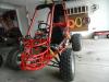


 (don't want to get it too dirty as it's going right up for sale)


