|
|
|
#101
 06-08-2016, 10:23 AM
|
||||
|
||||
|
You don't have to pull the engine. Just pull the cvt cover , clutch, belt than behind clutch will be I think 6, 6mm bolts. Remove the bolts and final drive access cover. Now you can clean and inspect the final drive gears and bearings.

|
|
#103
06-08-2016, 08:20 PM
|
||||
|
||||
|
Yep. Tom got you covered.
If anything went wrong, you'll see a lot of metal inside there or the gear lube.
__________________
My Yerban assault vehicle: 2.2mm stroker crank, 62mm Nikasil cyl, Taida large vavle head, American made valve springs, ported intake manifold, TM 28mm carb, stock CDI, Bando coil, TK exhaust, stock CVT except for the 14g sliders, 13/40 internal gears, 16T drive, 31T axle sprocket, 22" rear tires, and ONE BIG POTATO CANNON mounted on top..........
|
|
#104
06-24-2016, 09:03 AM
|
|||
|
|||
|
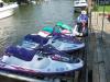
Went visited my wife's family in Texas. Day before was time to head back, they got a 4-6 inch rain. Water all over the place. So of course my son, and his cousins was wanting to go play in it. Told them, long as they clean the buggy after they are done. They did a OK job. But that Texas red dirt sticks really good. After got back had to take to car wash, and give it real good cleaning.
Kids really enjoyed the buggy. Small clip https://www.youtube.com/watch?v=cqs5XlOvG-c
|
|
#105
06-24-2016, 01:42 PM
|
|||
|
|||
|
Oh ya. last day there. in the very rear of the spider box, right next to where the engine mounts to the box. It broke there once before. I welded it. And did some re-inforcement to it. Think I showed how I did it, earlier in this thread. However, didn't seem to work. It's cracked just like it did last time.
Might be just a big weak spot. I have a another spider box. Think I should just use it. Re-inforce before putting it on the Dog.
|
|
#106
06-25-2016, 07:50 AM
|
||||
|
||||
|
__________________
My Yerban assault vehicle: 2.2mm stroker crank, 62mm Nikasil cyl, Taida large vavle head, American made valve springs, ported intake manifold, TM 28mm carb, stock CDI, Bando coil, TK exhaust, stock CVT except for the 14g sliders, 13/40 internal gears, 16T drive, 31T axle sprocket, 22" rear tires, and ONE BIG POTATO CANNON mounted on top..........
|
|
#107
07-14-2016, 07:20 AM
|
|||
|
|||
|
Geezz, one thing after another. For some reason, brakes stopped working. I tried to do a quick fix, and just tighten up the brakes. No good. So guessing need to bleed the brakes. Booster, is less then year old. So don't think it's that. I've been told once, that due to the small booster, the YD tend to get air in the brake lines for no reason. I cant think of anything I've done to it, that would cause it to get air in the lines.
Maybe because it's been in a lot of water lately? Anyone else have same issue? Brakes just going caput on ya?
|
|
#108
07-14-2016, 09:46 AM
|
||||
|
||||
|
All brake systems are sealed systems. If there is air in system it is either due to not completely bleeding all air out of system due to an air pocket or a leak in system. If you have a pedal but no breaks, likely cause will be either collapsed line or kinked line from master. If no pedal and master has not needed any fluid the master is the culprit.
|
|
#109
07-14-2016, 10:46 AM
|
|||
|
|||
|
I did switch out axles. But never had to mess with brakes, other then slipping the caliper off and on the disk. Do have petal, but no breaks. either way, will just need to bleed the brakes, and hopefully will go better than last time I had to do it.
Wondering if maybe the bleed value didn't come lose a little to let some air in the lines.
|
|
#111
07-15-2016, 01:25 PM
|
||||
|
||||
|
Trying using a vacuum style brake bleeder works very nice.
__________________
Hammer head Single seater know as herbie under construction Aluminum fuel tank, aluminum wheels, custom fuel/cargo rack, entire rewire, trail tech vapor, ported big valve head, a12camshaft, 12 gram sliders, straight intake, kirkey wide seat, front end extension. 4 point harness, welded cage. Hammerhead exhaust. Blade Single Seater Restore welded cage, engine build, new wiring harness/electric box, spun aluminum fuel tank.
|
|
#112
07-16-2016, 10:02 AM
|
||||
|
||||
|
Quote:
IE:If a master moves fluid down a 1/8 line 2" on a stroke. it moves a 1" round caliper piston 1". The same master pushing on a 2" piston only moves it 1/2" it's the surface area of the piston the fluid has to cover that makes the difference. In both circumstances The Fluid pressure is equal! Absolute fluid pressure is achieved and both pistons apply the same amount of force. In a closed brake system when the master is compressed, equal force is applied to all areas, the inside of the lines, fittings, etc. The only thing that gives is the caliper piston. Air bubbles rob the system by creating more area the fluid works against. Enough air bubbles in the system the fluid looses the ability to move the caliper piston enough distance to force the brake pad against the rotor. Your brakes go soft, feeling as though you have no pressure. So how does air seem to find a way into this system? Imo... it's the O-ring seals on the caliper piston and the wiper seal on the master push rod , If the system is not used for a few days or weeks the seals get stiff. After a stoke or two the seals loosen up but allows a microscopic amount of air to slip by until the seal is lubricated. After a time enough air gets in to start robbing volume. Cheap seals!
|
|
#113
07-17-2016, 04:06 PM
|
||||
|
||||
|
just went thru this with my daughters, which uses a YD master and caliper. caliper piston was stuck in the bore from lack of use. freed it by squeezing it withc my big c-locks, bled it and all is good to go again. worked fine for 3 years, she didn't ride much last season and it sat all winter.
|
|
#114
09-07-2016, 11:30 AM
|
|||
|
|||
|
Finally got brakes going again. In the end, used a clear hose, and fed it through a plastic bottle. And just had son, Keep pumping it, until got pressure back in the brakes.
Hit a sale just right, with a cupon. From Harbor Freight. Picked up a ATV wench. I can say, Don't think the Yerf Needs it. But when I get the FL 350 going, I can see using it on that. But would like to make it interchange able. A bolt on config of some sort. Anyone do this? I just don't see much room up front for the Yerfdog. So thinking of Making a removable bracket in the back. So can hook up a ball hitch, or slap on the wench. Anyone seen this done before? Idea's welcome.
|
|
#115
09-07-2016, 12:30 PM
|
||||
|
||||
|
Heck yea , receiver mount . You wouldn't have to use a 2" , but the smaller one with a plate welded on for the winch , and control box . Short length of square tubing front and back of each machine , hitch pin , plug like on a snowplow quick disconnect and away you go ! Watch it though I have same winches front and back on my King Cobra , and one on the back of the Magnum . You have to wire the power supply wires to a key'd or on - off switch power source , or simply disconnect one of the battery leads when not in use . That remote box constantly draws small amount of current , and will drain the battery in a week or less . I ran straight to the battery , simply welded a dime size washer to a battery bolt , spade end connector on the red battery lead . When done for the day - just reach down give the " wing nut " a turn , power cable slides off , and tighten wing nut . Or you'll lose it on the trail , Been there , done that .

__________________
2011 BMS KING COBRA 150 Sold YERF DOG SPIDERBOX's Sold YERF DOG 3203's. Sold MANCO SILVER FOX. Sold 2009 POLARIS 500 HO SPORTSMAN 4X4 2002 POLARIS 500 HO SPORTSMAN 4X4 2000 POLARIS MAGNUM 2X4 HALF A DOZEN CHEVY 4X4's NEED-MO-BUGGY 
|
|
#116
09-07-2016, 01:41 PM
|
||||
|
||||
|
Search Harbor freight badlands winches , in the mini buggy general discussion forum , pictures of how I mounted mine .
__________________
2011 BMS KING COBRA 150 Sold YERF DOG SPIDERBOX's Sold YERF DOG 3203's. Sold MANCO SILVER FOX. Sold 2009 POLARIS 500 HO SPORTSMAN 4X4 2002 POLARIS 500 HO SPORTSMAN 4X4 2000 POLARIS MAGNUM 2X4 HALF A DOZEN CHEVY 4X4's NEED-MO-BUGGY
|
|
#117
09-08-2016, 02:25 PM
|
|||
|
|||
|
Thanks
Interesting way of doing it. I was thinking more of down at the engine. Fab up some square tubing that mount to the engine cage. I'll half to see how much room I have in the back. Not sure if gas tank takes up to much room or not.
|
|
#118
09-10-2016, 12:29 PM
|
||||
|
||||
|
You don't have to pull the engine. Just pull the cvt cover, clutch then the final drive cover 6 bolts I believe,and inspect.If you used a good quality oil and did not drive too hard for too long it should be alright.
|
|
#119
09-10-2016, 02:17 PM
|
||||
|
||||
|
Uh -Oh ... I think someone just had a " Senior Moment "

__________________
2011 BMS KING COBRA 150 Sold YERF DOG SPIDERBOX's Sold YERF DOG 3203's. Sold MANCO SILVER FOX. Sold 2009 POLARIS 500 HO SPORTSMAN 4X4 2002 POLARIS 500 HO SPORTSMAN 4X4 2000 POLARIS MAGNUM 2X4 HALF A DOZEN CHEVY 4X4's NEED-MO-BUGGY
|
|
#120
12-19-2016, 09:46 AM
|
|||
|
|||
|
We got some snow this weekend. Was really wanting to take it out and play in the snow.
However, temps was in the Teens. I could start the engine, but could only keep it running at full choke. And had to keep gas on it, to keep it running. the warmest the engine got was around 150 F. Being that cold out, do I need adjust anything? Carb? what ever? or is it, they just don't like that cold of weather?
|
|
#121
12-19-2016, 10:34 AM
|
||||
|
||||
|
With it being that cold, i would adjust the fuel mixture screw for more fuel, and also try maybe a bigger main jet, and a bigger pilot jet. Buggy will make more power when its that cold out.
__________________
Hammer head Single seater know as herbie under construction Aluminum fuel tank, aluminum wheels, custom fuel/cargo rack, entire rewire, trail tech vapor, ported big valve head, a12camshaft, 12 gram sliders, straight intake, kirkey wide seat, front end extension. 4 point harness, welded cage. Hammerhead exhaust. Blade Single Seater Restore welded cage, engine build, new wiring harness/electric box, spun aluminum fuel tank.
|
|
#122
12-19-2016, 10:35 AM
|
||||
|
||||
|
Another reason why i cant wait to get the wideband hooked up on my buggy.
__________________
Hammer head Single seater know as herbie under construction Aluminum fuel tank, aluminum wheels, custom fuel/cargo rack, entire rewire, trail tech vapor, ported big valve head, a12camshaft, 12 gram sliders, straight intake, kirkey wide seat, front end extension. 4 point harness, welded cage. Hammerhead exhaust. Blade Single Seater Restore welded cage, engine build, new wiring harness/electric box, spun aluminum fuel tank.
|
|
#123
12-19-2016, 11:10 AM
|
|||
|
|||
|
Guess just need to get a fuel jet kit. Not sure what stock jets are in it. It's a 606 mini. Some reason I'm thinking a 190. But not sure.
So since air is cooler. More dense. More fuel may be needed?
|
|
#126
01-06-2017, 09:36 AM
|
|||
|
|||
|
Been a while since made a big purchase on the buggy. Been looking for while for some good shocks. Looking at "Fox" shocks, that others have suggested. However, came across some used "work" shocks that I think will work.
Yes, will need to do some adjustments to it. Rebuild kit. Move the mounting brackets for the back. They are dual action springs, and has adjustable pre-load. Picked them up for $250.00. From description, and talking with the guy, they in good working condition, and no flaws in the shafts. One does have a seal leak. I was planning on spending this much on a set of used "fox" shocks, then came across these, and couldn't pass them up, if they where in good condition. So got something to work on this winter. 
|
|
#128
01-06-2017, 03:47 PM
|
|||
|
|||
|
Your Spiderbox looks like a UFO at night! Very cool!
|
|
#129
01-09-2017, 08:26 AM
|
|||
|
|||
|
Almost got my winch placed. I have it welded to a reliever hitch. I can take it of. Or flip it over and have a ball hitch.
I welded reliever part to my support bracket. So by rights can take the entire thing off. Wasn't exspected for it to stick that far out. Maybe if I get it painted. And run the wires nice, won't look so junky. Reason I did like this, is so can use on other thing. I can even put it on my ranger. If for some reason might need it. Still work in progress. Winch can come off with 4 bolts. Think will setup it's own wire harness for the buggy. So can just plug in 2 wires, with a toggle switch. And ready to go. Need to make a plate to the support bracket I made. Therefore it will be mounted, all in one piece. Maybe even find some quick release pins for it. Actually put the buggy to work. We haul dead trees, for fire at night. With ball hitch, can haul use trailer to haul off trash. And when comes to deer hunting. Be really nice dragging the deer out of the trees with a sled. So I'll see how it works out. Might need it lower. Seen ppl place a extra cross member under the engine. On back end of the cage. Just behind the chain. Is that ok? Looks like it might an issue, if you need to remove the engine.
|
|
#130
01-09-2017, 09:25 AM
|
||||
|
||||
|
tkeagle , the cross member under the engine on the back bottom of the edge, to me is a very good idea, when I did it I can feel a difference in the rear when power sliding threw the turns, the rear felt stiffer and tighter, not so sloppy. Also it helps tie everything together back there, less chance of cracks in the motor mount and frame.
__________________
Hammer head Single seater know as herbie under construction Aluminum fuel tank, aluminum wheels, custom fuel/cargo rack, entire rewire, trail tech vapor, ported big valve head, a12camshaft, 12 gram sliders, straight intake, kirkey wide seat, front end extension. 4 point harness, welded cage. Hammerhead exhaust. Blade Single Seater Restore welded cage, engine build, new wiring harness/electric box, spun aluminum fuel tank.
|
|
#131
01-10-2017, 08:10 AM
|
|||
|
|||
|
OK, so you suggested it, even if not attaching a hitch to it. Just for better handling.
Rather then placing it on the bottom, matching the horizontal square pipe, like to put it up about 6 inches or less above it. So can mount the hitch to it, but avoid it being lower then the frame when I do attach it to it. Been while since I've removed the engine out of the cage. If I place a cross member about 6 inches above the bottom part of cage, will that leave enough room to drop the engine if need to again? Also, not sure if can do that. Not sure if being that much higher, if it would be hitting the chain. So may not be an option. However, will do as you suggest at least, and put a member back there. If it help support the cage from breaking, around the engine mount, I'm all for it. I can see that it helps out. Helps the cage from twisting.
|
|
#132
01-10-2017, 08:33 AM
|
||||
|
||||
|
Me personally i would weld the brace to where the bottom on both sides meet, thats what i did, and didnt get in the way of dropping the motor.
__________________
Hammer head Single seater know as herbie under construction Aluminum fuel tank, aluminum wheels, custom fuel/cargo rack, entire rewire, trail tech vapor, ported big valve head, a12camshaft, 12 gram sliders, straight intake, kirkey wide seat, front end extension. 4 point harness, welded cage. Hammerhead exhaust. Blade Single Seater Restore welded cage, engine build, new wiring harness/electric box, spun aluminum fuel tank.
|
|
#133
01-10-2017, 09:11 AM
|
||||
|
||||
|
I don't like that mount at all , looks like a diving board , it's gonna destroy at the mount at the swingarm . Also those winches need to be disconnected when not running . Either battery cable disconnected , or in line switch or solenoid as that remote power box draws power continuously when hooked up . Will drain a good battery in a day or two . Believe me , I have four of them . All I did was slot the spade terminals , and weld a dime size washer to the battery bolts , loosen a quick turn - slide power cables off , couldn't be easier .
__________________
2011 BMS KING COBRA 150 Sold YERF DOG SPIDERBOX's Sold YERF DOG 3203's. Sold MANCO SILVER FOX. Sold 2009 POLARIS 500 HO SPORTSMAN 4X4 2002 POLARIS 500 HO SPORTSMAN 4X4 2000 POLARIS MAGNUM 2X4 HALF A DOZEN CHEVY 4X4's NEED-MO-BUGGY
|
|
#134
01-10-2017, 09:42 AM
|
||||
|
||||
|
Quote:
__________________
Hammer head Single seater know as herbie under construction Aluminum fuel tank, aluminum wheels, custom fuel/cargo rack, entire rewire, trail tech vapor, ported big valve head, a12camshaft, 12 gram sliders, straight intake, kirkey wide seat, front end extension. 4 point harness, welded cage. Hammerhead exhaust. Blade Single Seater Restore welded cage, engine build, new wiring harness/electric box, spun aluminum fuel tank.
|
|
#135
01-10-2017, 02:23 PM
|
|||
|
|||
|
I really don't like it either. Looks trashy. When first started it, had different image in my mind. Only thing with this, I can completely remove it. Which is still what I want. Yes. I plan on putting a toggle switch in, so don't drain the battery.
Basicly it won't be attached until needed. Or use it for more of a work purpose. Why more interested in placing the hitch lower on the cross member. But still make it removable.
|
|
#136
01-11-2017, 08:35 AM
|
|||
|
|||
|
Need a little help on this. Got the work shocks. I'm going to half to do some adjustments. But one thing puzzling. I'm not a shock guy. But will be learning. On the bottom side of shock. Where bushings are. Looks like there is a bearing there instead? Is this a normal thing, or something previous owner did? They don't just slip out. Feels like they are pressed in. If this is a stock thing, how does it mount? Does the bracket need to go around the bearing? Or does bearing slip in between to plates just like if there was a regular bushing there?
Also. Looks like since the springs go all the way down to bottom of shock. Exhaust going to be in the way. My exhaust comes out the right side, rather then the left. If by chance to save some head aches, I'll just get a left side exhaust, if the pipe goes close enough in to the engine to clear the frame, where the bracket will be mounted. Can someone look, or grab a pic, to see if there exhaust stays tight enough to engine that it's not above the bottom frame of the cage where the shock bracket is. If need to, will heat up the pipe, and do what adjustments I need. But if there's a exhaust out there, that can avoid that, might rather go that route. 
|
|
#138
01-11-2017, 12:57 PM
|
|||
|
|||
|
You might be right. Could be just over sized sleeve.
Oh ya forgot one other question. Rebuild kit????? I'm guessing I should go to "works" for a kit? There are different types of kits. What type of kit am I looking for? I know will need one with new seals. But what else on standard kit should I look for? And what kind of info do I need to order the correct kit? Do I need the model #? Or do I go off of shock shafts size and ect..? Be little bit before I order. Like to get them mounted. And see if any other adjustments might need.
|
|
#139
01-11-2017, 03:25 PM
|
||||
|
||||
|
my thoughts wouldn't be so much the gears --if there's no metal in the bottom of the gearbox those should be ok. more of a concern as whether or not the bearings heated up too much and galled out. if they get too worn and sloppy on the output shaft then eventually the gears will bind up and kablammo ... just ask ckau about that. they're basic open bearings, h-fright has a blind bearing puller pretty cheap and a new output shaft seal while you're in there.
|
|
#140
01-11-2017, 04:32 PM
|
||||
|
||||
|
Quote:
|
|
#141
01-12-2017, 07:53 AM
|
|||
|
|||
|
Ya, after getting up on website, I can send them in, and have them put in a rebuild kit, for reasonable price. Plus can have them basically lighten up the shock, for around $65 each. So I'll just go that route. But again, need to get them mounted first.
After looking at it more, think best route to take would be to make the lower mount brackets high enough to set over the exhaust. If I try to bend the pipe in, might be to close to the engine case. Also, make a extended bracket with multi locations I can set the shock. Think seen x bird do that. So can arrange the pitch if need to for both lower and upper brackets. I've got pretty much any type of thickness scrap metal plates I can use to make the brackets. Just seems I keep adding weight to the thing. One of these days, need to do some other mods to up the HP in it.
|
|
#142
01-23-2017, 08:14 AM
|
|||
|
|||
|
Got to on YD this weekend. Removed old shock mounting brackets, and started to fab up some new ones.
Found some stout 3/8 stainless steel angle. Cut them in half. Then used back side of the other piece to finish the "U". Still half to cut off the back side of the remailing angle. But will still leave me some good scrap for later projects. Where I got the shock placed is about best angle I can see. Matches close to where the stocks was. However, figured I can't just build the bracket over the exhaust pipe. Just to high. And would force to make the pitch pretty vertical. Guess will take to exhaust shop, and have them bend it for me. There still plenty of room to move it in, and won't be to close to engine. Will wrap in heat tape anyway. Made the brackets long enough also, so can put a few hole locations, so can adjust pitch, or even different length. If need for some reason. Only thing I an issue, is putting the brackets to far back, they will be over where the bearing brackets. Not sure it that a good idea or not. Just seems like might be headache later. I'm trying to set this up right, so will be doing this ONLY ONCE! .Any thoughts, please reply. Hopefully by end of this week, I'll be able to take a test run. Last edited by tkeagle; 01-23-2017 at 08:17 AM.
|
|
#143
01-23-2017, 08:42 AM
|
|||
|
|||
|
One other thing, forgot to ask. When drilling the holes for the brackets. The location where I got the shock placed in the pic, is where the bottom of shock and bracket will be in front of the Bearing brackets and top will be right on top of the horizontal bar back behind the seats. Should I make it adjustable so that if I want to change the pitch, it would be more vertical? I'm just guessing that, so that maybe can utilize more of the shock? Or better to have option to make it more horizontal, so the bottom of the shock, sets further back on the swing arm? Like said, trying to do this right the first time.
|
|
#144
01-23-2017, 10:45 AM
|
||||
|
||||
|
For locations, being on top of the bearing hangars is ideal, since that's where any rising force from the tires/axle will come in. putting the mounts in between the pivots and hangars moves that force to the swingarm bars and stresses them. But they are beefy enough to handle it if you need to go there. For the most part, this line of thought primarily comes into play on hits that cause the shock to bottom out. likewise up top, you should add some tubing to the rack tube that carries up into a solid junction. View the force as an arrow going up through the shock mounts, and think about where it ends up. for my builds i do beat the living heck out of my suspension so i make sure the impacts do not end up in unsupported tubing runs. from day one of its life with me --and even before, as a 3203, the rear shocks were cracking the frame tubes, likewise with the rear shocks on spiderboxes and just about all other buggies. the upper mount sitting on a straight tube run with a shock driving into it is a far from ideal design.
As you can tell i love to tinker with things, for me, rebuilding/tuning the shocks gave me a lot more knowledge and ability for the future. I still strongly recommend doing them yourself, they are not difficult to do and add to your arsenal so to speak. I did have a long background with working on a variety of mountain bike suspension forks and rear swingarm shocks from nearly 30 years of racing them both xc and DH and also was deep into the automotive fields before i got into buggies. As far as getting close to vertical, as long as the swingarm cannot kick the shock beyond the peak of the arc and make it unload/push with the result that the swingarm locks upwards, that's what you want. the more you "lay" the shock off vertical the more stress you put on the shock shaft, it increases stiction, impacts damping and can lead to shaft bending and wear on the side seeing more thrust. Last edited by x-bird; 01-23-2017 at 10:50 AM.
|
|
#145
01-23-2017, 02:01 PM
|
|||
|
|||
|
Thx for the input xbird. That helps. Gives me a better idea which way to go.
I'll take your advice, and beef up the top brackets locations. Got any ideas or pics on how to do that? Only a few options I can see. Maybe some triangle Platts at lower and upper junctions. Could place a horizontal support under the top junction. Could weld some Platts on the vertical square tubing to beef up the strength.
|
|
#146
01-23-2017, 03:27 PM
|
||||
|
||||
|
from what i could tell, you're looking to set those uppers under the most rearward tube of the cargo rack which is just hanging out there relatively unsupported. think you'd bend that with even mild riding after awhile.
i was looking at your pics trying to spot where the mount is at in relation to the cargo frame and fuel tank. if you can make two tabs for the mount on the underside of the tube then on the opposite side of the tube, have a tube go straight up to the top of your cage, or on an angle to the upper corner of the cage, you'd be good to go. can't tell if that new tube would have the room to get by the tank.
|
|
#147
01-23-2017, 03:32 PM
|
||||
|
||||
|
as far as that exhaust pipe goes, if your welding skills can handle thin gauge, cut a little angle chunk out of it to tighten it towards the engine and weld the cut shut. a 1/8th wide cut will move it a pretty fair amount, so don't take too wide of a wedge out of it. Do it all the time with exhaust pipes.
Last edited by x-bird; 01-23-2017 at 03:40 PM.
|
|
#148
01-23-2017, 03:38 PM
|
||||
|
||||
|
ok, i see now where you're at with the upper, that's a hmmmm .... LOLthe reason the original upper tabs are so long is to spread the load. a triangular plate 1/8th to 3/16ths thick across the top about 4 inches wide with a pair of 4-5 inch long mount plates running down the tube to about where the originals were would help that out.
If you start jumping this thing (no one does that, right??) you're gonna have to keep an eye on that frame rail.
|
|
#149
01-24-2017, 08:11 AM
|
|||
|
|||
|
Yep. As far as uppers, that's about the only place can mount them. Unless I do a added rehab of frame.
Pics are of semi finished brackets. Still need to drill the holes. And will need to cut some angles in the other ones for the shock clearance, since they sitting at an angle. One set is 5 inches. Other is 4. Was going to use the 5 inche ones for bottom. But now might reverse that. What you described is pretty close to what I was thinking for reinforcement. I'm not that good at welding. But my buddy is. So that is an option. But if can flip a shop a $20.00 and he can bend it, without cutting it, will go that way. Jumping? What you talking about? You think I built this toy for my younger inner child? To go out, and see what cool crap I can get this thing to do? Then when it breaks, I enjoy sitting out in garage trying to fix it, and make it better? So you saying it's not only for my kids? Hmmmmmmmmm. Ok, got me. 
|
|
#150
01-26-2017, 08:20 AM
|
|||
|
|||
|
Well, daughter was sick yesterday. So gave me a chance to do some work.
Took it to bumper to bumper. Guy there cut the pipe, and welded to an angle that worked. Nice guy, didn't even charge me. Continued to work on the brackets. Longest and hardest thing to do, was drill the holes by hand in the metal plates No drill press. That's some strong ass metal. Then realized after making a second set of holes, so adjustmentshe could be made, just wasn't enough room. Needed to cut a chunk out for some clearance on the bottom of the shock, due to the pitch. Shock was bigger then thought, needed about another inch of bracket. Ohe well. Can and it later. The lower part of shock will be just a little forward of center of axle. The top point will be a little above the horizontal cross tube pipe. So will need to reinforce that. All in all, think going to turn out good. The shocks will be setting more vertical then before. Plus the bottoms are very close to center of axle. Just need extra support for top brackets. Then make sure I get everything good and even, before I start tacking it together. Then I'll remove hitch, and get it down lower.
|
|
#154
01-27-2017, 01:48 PM
|
|||
|
|||
|
Ok. What I thought, but never know.
It's time consuming figuring how and where to reinforce. Only have about 1hr of sunlight left after work. So very little gets done during work week. Can tell, I'm going to have some tight spots, getting a weld in.
|
|
#155
01-29-2017, 07:04 AM
|
|||
|
|||
|
Spent all day working on it. Didn't help had to run a town over to pick up welding wire.
At one point, thought it was ready. Then realized the a arms was lvl with frame. It hit me, once I let it down on its own tires and wieght it would lower. Not a bunch, but enough, if would have dropped it way it was, the a arms would be low then the frame. Not what I wanted. So had to lower the spider box to best guess. Which did chance the bracket location. On previous pic. The first setup I had the top half of thr upper brackets sitting about 1.5 inches above the back horizontal cross member. And would need to fab up some extra bracing. Now it sits just slightly above. So going to use some of the same angle iron I used on the shock brackets, and weld it around the cross member to the shock bracket. Also will add some triangle bracing under the member, where the square tubing meets. I'm thinking that should be good.
|
|
#156
02-01-2017, 11:13 AM
|
|||
|
|||
|
Well. Got brackets welded in. Was kind of a pain. I would say I'm still a beginner. Need to do some clean up. Then get them covered with epoxy.
Got the winch bracket off the top brace. And going to reinforce that top motor mount on back side with some angle iron I have left over from the shock brackets. Using angle iron for the back motor mount on the cage... I weld it same way I did the top shock bracket? Weld across the top and bottom. Then weld on each end. Or should I weld one one more plate under that cross member?
|
|
#157
02-03-2017, 09:44 AM
|
|||
|
|||
|
Yahoo!! Mission accomplished!
Think this is going to make a big difference. Before with the other shocks from BD, I had to pretty much hope off the ground and push down, to get the springs compressed. With these, I can take one hand and just push. They compress, and come back up at a slower pace then then others. Can't wait to get everything back together, and test them out. Going to start looking for better set for front now. But looking what options I have for the front. Very limited on the length. Will see what can find in fox, or works. With the extended bracket on the bottom. Think 12.5 is what I measured for max length. That said, have a used back set of shocks up for grabs. And a front set, never really used. Both from BD.
|
|
#159
02-03-2017, 01:30 PM
|
||||
|
||||
|
looks really good tk, think its time for a new uni filter though lol.
__________________
Hammer head Single seater know as herbie under construction Aluminum fuel tank, aluminum wheels, custom fuel/cargo rack, entire rewire, trail tech vapor, ported big valve head, a12camshaft, 12 gram sliders, straight intake, kirkey wide seat, front end extension. 4 point harness, welded cage. Hammerhead exhaust. Blade Single Seater Restore welded cage, engine build, new wiring harness/electric box, spun aluminum fuel tank.
|
|
#160
02-06-2017, 01:36 PM
|
|||
|
|||
|
I never did get the dog out over the weekend. It nice out, so decided to update some stuff, since had fenders off. Took off the hitch. And reinforced the back cross member that holds the engine hanger. Turned out pretty good I think. Looks so cleaner. Also noticedo the chain guard broke, so had to clean up and weld it also.
I didnt realize it. Until yesterday. I got weld splatter on the brake disk. Bad enough, need to clean it up before taking it out. Any idea best way to do this? Was suggested using and being careful with a chipping hammer. Seems like that might take awhile. I have a 4 1/2 inch grinder. But room is tight, and don't know if can use it, without damaging the disk?? Have a Dremel, but wondering if still could do damage?? Since it's turned cold, I can't keep the engine started. Starts good, then rpm goes down, then dies. Wondering if have air leak somewhere. Haven't had any issues til now, so not sure what has changed. I'm getting some white smoke out of exhaust. But think it just cold. But can't tell for sure, since really not staying started long enough to warm up.
|
|
#161
02-06-2017, 07:44 PM
|
|||
|
|||
|
How much bird poop are we talking about? The tiny little balls usually come off really quick without using a chipping hammer. If you have a flat bastard file, you can use it as a chisel - just place a rag between the file & rotor and keep the file FLAT on the rotor when you tap it with a hammer.
But without actually seeing the splatter, it's tough to give advice.
|
|
#162
02-12-2017, 08:38 AM
|
|||
|
|||
|
the splatter was very small. I took edge of some thin metal and went across the disk. put a thin rag in front of it. did a pretty good job. Thanks for the idea.
I finally got everything back together. There for while, I was concerned as if engine was running good or not. Had a day with high in mid 70's. Got some fresh gas, and was able to get it started long enough to get it running down the road. Got it opened up. cough and putted alittle, before could get to full speed. Once I did, ran like a champ. Think it had cabin fever.  As far as the ride, with the different shocks? I forgot to grab the seat cushion's for the seat. So might have felt more than normal. on the smaller stuff, I could feel a softer ride. But not sure about some bigger holes or bumps. When got it on the dirt road, felt like a car ride going down the road. Had my son get in it, and see what he thought. He thought it felt alot better. Keep in mind he 100 lbs lighter than me. When I saw him drive off, I kept an eye on the shocks. Looks like they hardly moved. and was an area that has some pretty good chop to it. Had him do it multi times, and still looked like they hardly moved. From what it came off of, was guessing they might be to stiff. Now if the shocks are not fully charged, like they should be, would that affect the performance that much? Here is the thing, from the previous shocks I had on it, I could tell these are much softer. At least on the top end of them. When I really try to push down on them putting my weight on the very back of the cargo rack, I can feel them stiffen up fast on the last 1/3 of the down stroke. I tried to do the same thing, but this time pushed down on the cross bar right behind the seats. And it was much harder to get the shocks to compress. Alot harder. noticed also, that I couldn't actually get and compression on the springs them self. Was just the cylinder that moved. not really any movement on the springs them self. I really couldn't tell for sure, but was trying to guess how much movement I actully got on the shocks. from what I guessed, didn't even get 1/2 of what they can do. But again that was a guess. Going to try again today, if temps get up good enough to keep it running good. This time take it out where got some bigger stuff, and a few small jumps. See what I can get the shocks to do. Will try to video of the movement. And somehow mark, how much movement I'm really getting. I'm guessing best way to do that is to slide the bottom boot up to the top, and see how far it slides down on the shaft? before I change the performance of the shocks, want to see what they are really doing. That said, really leaning toward getting the tools needed to work on them myself. I've got 2 buggy's and 4 sets of shocks, I will be working on, so in long run, think be worth the effort to learn it. if do need to change the performance of shocks, it could get pretty expensive really quick sending them in. Which defeats the purpose of buying used. Think going to adjust the fronts also. watching them also, looks like I got to much preload on them. only time they seem to compress is on a sharp turn. which doesnt happen much unless trying to do something. Will play with that also.
|
|
#163
02-13-2017, 08:19 AM
|
|||
|
|||
|
Didn't get done what I wanted. Had to wait til temps warmed up. So put some gussets on the front end.
There was a small Crack on one side. Since had time, jumped in, and took care of it. Then when did get buggy out, with the first round with my son driving, gas line started leaking pretty bad. So shut it down for the day. Going to start another small project. Been bothering me. There is no kind of mini dash, or console in these yerfdog. With the extra lights, trail tech, and ect... the front pit looks trashy, with all the wires. Any one make some sort of front panels for the dogs before? Any pics. There is just so many ways can go with it. But that steering column is in the way, to make a straight panel between the 2 upper roll bars. Wondering if anyone has tackled this feat yet?? I looked at it, while sitting in drivers seat. Seems like plenty of room to make it under the main cross bar. If want. Or could set it on top. But then would need to figure out for something on the head lights. Any thoughts, or better pics would be nice. Want it so, have wires hid, from drivers seat and looking from the front. Try to make it look natural. If that is the correct word I'm looking for. Thanks Last edited by tkeagle; 02-13-2017 at 08:23 AM.
|
|
#164
02-13-2017, 12:49 PM
|
||||
|
||||
|
Quote:
__________________
Hammer head Single seater know as herbie under construction Aluminum fuel tank, aluminum wheels, custom fuel/cargo rack, entire rewire, trail tech vapor, ported big valve head, a12camshaft, 12 gram sliders, straight intake, kirkey wide seat, front end extension. 4 point harness, welded cage. Hammerhead exhaust. Blade Single Seater Restore welded cage, engine build, new wiring harness/electric box, spun aluminum fuel tank.
|
|
#165
02-13-2017, 02:48 PM
|
||||
|
||||
|
tk, i was thinking a little, if i where you, if you where going to go as far as making a dash for the yerf, i would recommend a entire rewire of the buggy and do something with a fuse block and ground block. I now its a little bit of $ and some time, and figuring out, but its well worth it if you ask me, since the stock wiring on these buggies to me is crap.
__________________
Hammer head Single seater know as herbie under construction Aluminum fuel tank, aluminum wheels, custom fuel/cargo rack, entire rewire, trail tech vapor, ported big valve head, a12camshaft, 12 gram sliders, straight intake, kirkey wide seat, front end extension. 4 point harness, welded cage. Hammerhead exhaust. Blade Single Seater Restore welded cage, engine build, new wiring harness/electric box, spun aluminum fuel tank.
|
|
#166
02-13-2017, 03:45 PM
|
|||
|
|||
|
Actually, when I had it apart, I made a entirely new harness for it. Bigger and better. Covered it all in heatshrink, and ran it from front to back inside the tubing frame. So that taken care of. But since then, everything added, has been sliced in. Why want to clean up. Just a few years, the weather has put a toll on the exposed wiring up front. Also want to add a light bar up top, for hunting. Add that to everything else, only have one switch to turn on the trail tech. Head lights and the upper and lower leds. Plus if add a winch to it. Found a nice outdoor marine control center I like. But if going to do that, might as well do it nice, and clean it up.
However, adding electric box for the back, should be done as well. Fuse block for both, be wise too. More then smoked some wires, on stupid stuff. Thanks for the input. Like to make so the trail tech is at least some what protected from rain. Know it should be water proof. But even after a rain, it glitches now and then, if get a big rain. Seen what he used, basicly Tupperware to help protect. So that could be used.
|
|
#167
02-16-2017, 08:21 AM
|
|||
|
|||
|
Got some 1/4 angle to use as a support for lower cross member. Also going to mount a hitch on it. Will look much more clean. Also found a Crack in the front tubing. Welded the other one a few years ago. Think going to put a few gussets on both of them.
Replaced fuel lines and filter. The fuel out on tank, is almost straight above the carb. Any one have any issues of the fuel line kinking if the shocks compress enough over rough terrain? The storage rack comes down.
|
|
#168
02-16-2017, 10:09 PM
|
|||
|
|||
|
It's hard to tell from the picture, but your fuel line looks too short. Even if it had more of an "S" bend to it, that might help a lot. Like I said though - might just be the picture.
TK, my Dog had cracks along both of those tubes. After laying a weld over the cracks, I cut some 1/4" plate to make some gussets. While I haven't had my YD nearly as long as you, I read about the cracks (and gussets) here on the forum.
|
|
#169
02-18-2017, 08:26 AM
|
|||
|
|||
|
Got lower brace installed. Took long then thought, but wanted it to look as if part of buggy. So did alot of cosmetics to it. Put 2 braces on both sides to in close the area attached to the frame.
After getting it all tacked good, had 2nd thought of should have went further down the frame. But honestly, should be more then enough. If that 1/4 by 2 inch angle breaks, I'm in world of hurt in other places. I've put a good amount of extra steel on it, over last few years. I've got some good 1/8 aluminum sheeting. Think might be time to use, get rid of the metal skid plate, or floor, and replace with aluminum. Should give get me some wieght back. I hope.
|
|
#171
02-19-2017, 10:52 AM
|
|||
|
|||
|
Finally got the buggy out to test the shocks. Must say I can tell a difference for the better. Was able to push it father with improved ride. Using the boots asale reference, the shocks was used a little less then half of what they cabiable of. This was at our place where it is ridden most of the time. Then took out to other location where there is more deeper dips and decent humps. But really no jumps. Boots moved little half way down. That was much could do for the day. Wasn't able to get a chance to push it anymore. Haven't found a good location to jump. Even a small one. One place that think is really good, pitches the buggy little to the left right before the top of Hill.
That said, with still around more then 1/4 of shock can be used, are they to stiff? Guess like ppl thoughts on it.
|
|
#172
02-19-2017, 02:14 PM
|
||||
|
||||
|
an "ideal" setup would be to shoot to bottom out the shock on your roughest hits. however, that's following a "track tuning setup" mindset. Just like with an engine on racetrack when gearing is chosen to allow the driver to hit the rev limiter at certain points to optimize lap times likewise suspension settings can be approached that way. however, for a good all around recreational rider, having some shock travel in reserve is not a bad thing.
|
|
#173
02-20-2017, 07:26 AM
|
|||
|
|||
|
Well. Overall happy with shock setup. If come across some rougher ground, or want to get more Wild with it, it's setup pretty good as is. But if want a smother over all ride with the area it's normally on, could use some tweaking. Guess will depend on how much it will cost to do that tweaking.
Now to a point where start working on some sort of dash. Which guessing going to be a long possess then Id like.
|
|
#174
02-23-2017, 04:21 PM
|
||||
|
||||
|
the vice blocks i was talking about, mine are similar, but much older and well abused.
http://www.ebay.com/itm/Earls-Perfor...023840&vxp=mtr
|
|
#175
03-01-2017, 07:59 AM
|
|||
|
|||
|
Thanks bird. That helps.
Got some new goodies. For next project on yd. Going through electric system, cleaning it up, and make it safer. Got a 22" light bar. A sealed electric box. And a marine control center. Going to clean the wires going back to battery. With the control center, can run good positive, and one ground, which will run through frame tubing. And from those 2 wires, can run rest of stuff from the control center, that can run from 6 switches. Also usb, and extra power. Plus volt meter. Will get a neg/pos. Block out. This will keep me busy for while. Anyone that has light bar. These have a rubber bushings below the mounts, between the frame. I'm mounting on round tubing. Looks better and fits without the rubber bushings. They there just to protect paint surface. Or they needed to shock absorption? Should I use the bushings? Or does it matter? Thanks.
|
|
#176
03-05-2017, 11:14 AM
|
|||
|
|||
|
Little update. Started working on control panel up front. Think might be best location. Just tacked now. Will be a few inches higher, in final placement. Checked clearance for me, wife, and kids. Driver and passenger side. Seems good. In final product will shave down brackets so not sticking out, and no sharp edges.
Got light bar mounted. And ran the power inside the upper roll bar, leading down to front of buggy. Got all my trail tech wires run inside the tubing of outer roll bar. From very back, in front of engine, to the front. Where the major junction is. Also ran a 10 gage primary power lead. And a extra 14 gage blue wire with in line fuse. Just in case need for some reason. Figured if in there doing it. An extra power couldn't hurt. Still haven't messed with the back wiring yet. This will still take some time. The volt gage is pretty cool. Powered it up. Runs 12.4 without engine running. Flip the light bar on, and gage jumps down to 11.8 volt. Nice option to have.
|
|
#177
03-05-2017, 11:20 AM
|
|||
|
|||
|
On side note, would prefer to set control center on top rather then below the main cross bar. However would be pretty hard to make a cover for the back. And look wierd sticking out on top of bar. Unless I make some kind of front hood of some sort. Pretty cool. But alot more work. Not sure yet. But think can make it work, where it sits now.
|
|
#179
03-07-2017, 07:48 AM
|
|||
|
|||
|
Its still kicking. Took buggy out really for first time this year, for some joy riding. And seems to be at same location, 2 of the younger kids was cruising in it, and rolled it going around a turn. Both kids fine. Not a scratch on either one. So all good there. Parent of the kid driving was there. At first she was spooked. But then realized everything good. Kids did as been told over and over again. Hands stay inside the buggy.
She was amazed how I was just able to roll it on it's wheels, jump in, start it right up, and drive off. Just some touch up paint, and maybe bend back a fender alittle. But noticed the top roll bar, on drivers side is bowed in. Not sure if can bend it out, or just need to replace it. Had the light bar just installed, don't like did any dmg at all to it. So all good. Just hope this isnt' a hint of what's coming up this summer. .Seems like the kids don't believe me, when I say, you got to take it slow on the turns. Seems like they always find out the hard way, by what I mean.
|
|
#180
03-07-2017, 07:53 AM
|
|||
|
|||
|
Looking into really getting a different gas tank. Already told wife. Just don't like it where it sits. On top of the cargo rack. Going to get a smaller one, and mount it under the rack. I know it may not make a huge difference on the center of gravity. But think any little will help.
|
|
#181
03-07-2017, 07:46 PM
|
||||
|
||||
|
Quote:
__________________
Hammer head Single seater know as herbie under construction Aluminum fuel tank, aluminum wheels, custom fuel/cargo rack, entire rewire, trail tech vapor, ported big valve head, a12camshaft, 12 gram sliders, straight intake, kirkey wide seat, front end extension. 4 point harness, welded cage. Hammerhead exhaust. Blade Single Seater Restore welded cage, engine build, new wiring harness/electric box, spun aluminum fuel tank.
|
|
#182
03-07-2017, 08:02 PM
|
||||
|
||||
|
Quote:
This pic gives a example of the wheelbase gained on a yerf swing arm.
|
|
#183
03-08-2017, 08:36 AM
|
|||
|
|||
|
Gas tank is like 3 gals. It's a spun round aluminum. It's pretty tall. To tall to go under the rack. Took it off my fl350. And was going to use stock gas tank on it, and hook up fuel pump. I haven't got it started since trying going back to stock. Think it's been set up for gravity feed. So will put that tank back on it, and buy new one for yerf. Seems like all I'm finding in smaller tanks are round spun. Like to find a more square one. To make sure have enough clearance between gas tank and engine. But if need to go round. Will just go smaller one, no more then 6 inches thick.
Would love to go that axle setup. I will get to it. But have done enough to dog already this year. Really want to get into the fl350. Goal it to get it running good, and brakes working. Will need at least new front tires also. Just want to ride it this year. Then winter, get into more. Wife been wanting to ride it. She bought it for me. She wants it used. .
Last edited by tkeagle; 03-08-2017 at 08:39 AM.
|
|
#184
03-08-2017, 10:01 AM
|
||||
|
||||
|
rectangular shallow fuel tanks. dk if they have the capacity you're after ....
www.*************.com
|
|
#185
03-11-2017, 04:26 PM
|
|||
|
|||
|
Looked at those tanks. Really not what looking for. But thanks. Just ordered a alum spun tank. Where I've got it in mind, should work well. It a 4x15... 3/4 gal. Was hoping for at least a gal. But oh well. Still cover a full day ride for us.
Been working on wiring for few hrs a day. Might look like a mess, but it's much cleaner then had it. Instead of just a slice and tape, most of it is sod. And all protected connections. Almost got everything connected. Then next task is to make my electric box in back. And make cover for wires up front.
|
|
#186
03-15-2017, 09:51 AM
|
|||
|
|||
|
Started on the back wiring. Getting all the main wiring connections inside the box is going to be tight. I have the 11 pole. The plug and play from BD. Thou nice, it adds alot of clutter. I can save alot of room if take out the plug in plastic connections, and just wire it with good quality round protected connections.
I've had to take zip ties to keep the clips together. They not all a tight fit. So is any reason not to get rid of the plastic clip Connections? I guess other then needing to place the system, and be able to just clip a new one in. Like said, the box is tight, and wires going to be crossing over each other alot. But no difference then how was before. But thinking a good protected connector on each wire, would be better. Or not????? Guess is my question. The new box is going to be placed at same location as old. When I get my block out, would be easy enough to unplug the wires I need to protect. Add some extra wire, then plug back in to the wire system. Going to mount the block out behind the seat, on the frame. Again, any reason why this may not be a good idea?
|
|
#187
03-15-2017, 10:35 AM
|
|||
|
|||
|
Looking more at the block outs. Looking at 12 circuit, with neg. And cover on amazon.
I'm I trying to do to much? Meaning just use the block out to make all my connection to the system? So saying in stead of connecting all my positive connections with a splice, then run to block out. Splice the connections with the block out. Wires for the sator, starter, CDI. Ect... ??????
|
|
#188
03-15-2017, 02:46 PM
|
||||
|
||||
|
I wish BD or someone sold an upgraded wire harness kit with a water tight fuse box, decent connectors & wire for our GY6 type buggies.
|
|
#190
03-16-2017, 07:30 AM
|
|||
|
|||
|
What I'm trying to do my self.
Will have the siliniod and CDI in water proof box I got. And with the splices I make, keep them inside box as well. All my wiring from the front going back will be able to connect directly to the block out. Just will need to lengthen the engine harness wires to reach the block out. Thou one thing not for Surest about. It has a pos/neg block out. From what I've read, if you connect the battery, then rest of circuits can run off that. But will still need to find ground for each one. Has total amp of 100. Each circuit can handle 30. Do I run my battery to block out. Then run it to starter. Or just run wire from one of the other end 30 amp circuits to the starter. ??? On driver side got my main power wires running inside the frame, to the back. The power on. The starter. A extra power wire for the lights that was on it. And a ground wire. Will hook them up each to a 30 circuit. And bring the wires need from engine to the block as well. On passenger side, have my trail tech wires. And 2 powers. Main power running control center up front. And the other power for trail tech. By rights should just hook those 2 to block, and be good. By rights, a 6 circuit block should work. Might go that route. But the 12 is only $10.00 more. But of course bigger.
|
|
#193
03-16-2017, 09:40 AM
|
||||
|
||||
|
Yerf dog is ac cdi, i would recommend more then a 6 gang power source, go with at least 8 trust me.
__________________
Hammer head Single seater know as herbie under construction Aluminum fuel tank, aluminum wheels, custom fuel/cargo rack, entire rewire, trail tech vapor, ported big valve head, a12camshaft, 12 gram sliders, straight intake, kirkey wide seat, front end extension. 4 point harness, welded cage. Hammerhead exhaust. Blade Single Seater Restore welded cage, engine build, new wiring harness/electric box, spun aluminum fuel tank.
|
|
#194
03-16-2017, 09:43 AM
|
||||
|
||||
|
Im sure the 12 gang power source is really big. Are you doing a ground block also? Or grounding everythingnto the frame? If your grounding to the frame, then just take measurment of the 12 gang power block, and measure what ur box is and see if it fits inside.
__________________
Hammer head Single seater know as herbie under construction Aluminum fuel tank, aluminum wheels, custom fuel/cargo rack, entire rewire, trail tech vapor, ported big valve head, a12camshaft, 12 gram sliders, straight intake, kirkey wide seat, front end extension. 4 point harness, welded cage. Hammerhead exhaust. Blade Single Seater Restore welded cage, engine build, new wiring harness/electric box, spun aluminum fuel tank.
|
|
#195
03-16-2017, 10:33 AM
|
|||
|
|||
|
Yes. Going with ground block also. Will connect the grounds in back. Or for the engine to the block. Grounds up front will go frame. I do have 1 ground from the front to back. Could connect that to block, and use that as primary ground for front. Be alot of wires connected to one thou.
|
|
#196
03-16-2017, 11:04 AM
|
||||
|
||||
|
Quote:
__________________
Hammer head Single seater know as herbie under construction Aluminum fuel tank, aluminum wheels, custom fuel/cargo rack, entire rewire, trail tech vapor, ported big valve head, a12camshaft, 12 gram sliders, straight intake, kirkey wide seat, front end extension. 4 point harness, welded cage. Hammerhead exhaust. Blade Single Seater Restore welded cage, engine build, new wiring harness/electric box, spun aluminum fuel tank.
|
|
#197
04-03-2017, 09:27 AM
|
|||
|
|||
|
Wiring coming along. But kind of disappointed. Got 5 grounds to the block out. Which nice. Cleaned it up a bunch. Instead a glob of wires on one ground.
But can on use 3 positives. Block is a 30 amp max. Thought would be plenty. But the wires for CDI, sator, and starter, just blows fuses. 30 amp. Can't think the engine would need over 30amps. Or would it??????? Only thing I can think of is since the CDI is AC, but block out is DC. That's why can't use it, with those connections?????????? However did get all of front wiring done. Just need to finish the back cover for the control station. Going to look pretty good. Got new gas tank mounted. Turned out pretty good also. But need a "L" shutoff off valve for it.
|
|
#198
04-03-2017, 09:52 AM
|
|||
|
|||
|
Almost done with the cover for the control center up front. Will line the inside of it with something, since fabbing it out of thin gage steel. It make it less conductive. Any suggestions? Going to be alot of wire splices in it.
At first had the white box turned long ways towards the seat. Then noticed that it could hit the frame behind the seat, if shocks came all the way down. So had to turn it. Had just 2 tabs on the rack for gas tank. But then realized be to damn hard to line everything up straight, trying to make 4 tabs that line up perfect. So again started over, and had some round tubing. And welded one piece for each side, to very back of rack, and bottom piece. Now can use the full area of rack again.
|
|
#200
04-05-2017, 09:46 AM
|
|||
|
|||
|
Finally coming together. Got back guard fabed up for all the wires up front. Add a few supports. Clean it up. Spray some rubber coating on inside and paint. Trickiest thing was to build it so completely detachable. So when need to mess with anything inside.
All the lights are hooked up. Tucked in and working. Also made a mounting bracket for the trail tech on the driving colum. Made it easier to mount the control station. And easier to see from driving seat.
|
 |
| Thread Tools | |
|
|